Form No. 3393-956 Rev B 8-Blade Radial Reel, 8-Blade Forward Swept Reel, or 11-Blade Forward Swept Reel DPA Cutting Unit with 7in Reel Reelmaster® 5010-H Series Traction Unit Model No. 03638—Serial No. 315000001 and Up Model No. 03639—Serial No. 315000001 and Up Model No. 03641—Serial No. 315000001 and Up Register at www.Toro.com.
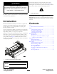
This manual identifies potential hazards and has safety messages identified by the safety alert symbol (Figure 2), which signals a hazard that may cause serious injury or death if you do not follow the recommended precautions. WARNING CALIFORNIA Proposition 65 Warning This product contains a chemical or chemicals known to the State of California to cause cancer, birth defects, or reproductive harm. Figure 2 1. Safety alert symbol This product complies with all relevant European directives.
Safety which could get caught in moving parts. Always wear long pants. Wearing safety glasses, safety shoes, and a helmet is advisable and required by some local ordinances and insurance regulations. This machine has been designed in accordance with EN ISO 5395:2013. • Remove all debris or other objects that might be picked To control hazards and prevent accidents, it is essential that those who operate, transport, maintain, and store the machine be aware, concerned, and properly trained.
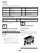
Setup Loose Parts Use the chart below to verify that all parts have been shipped. Procedure Description 1 2 3 4 Use Qty. Cutting unit 1 Inspect the cutting unit. No parts required – Use the kickstand when tipping the cutting unit. No parts required – Adjust the rear shield. Straight grease fitting O-ring 1 1 Install the loose parts. Media and Additional Parts Description Parts Catalog Operator's Manual Use Qty. 1 1 Review the material and save it in an appropriate place.
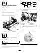
3 Adjusting the Rear Shield Figure 5 No Parts Required Procedure 1. Remove and discard the set screw on the reel-motor side-plate (Figure 6). Under most conditions, best dispersion is attained when the rear shield is closed (front discharge). When conditions are heavy or wet, the rear shield may be opened. 4 To open the rear shield (Figure 4), loosen the cap screw securing the shield to the left side plate, rotate the shield to the open position and tighten the cap screw. G028640 Figure 6 1.
Product Overview Rear Roller Brush Kit: A high-speed, high-contact brush that keeps the rear roller free of grass and debris, which maintains a consistent height of cut and prevents clumping. This leads to a better after-cut appearance. Roller Rebuild Kit: Includes all the bearings, bearing nuts, inner seals, and outer seals required to rebuild a roller. Roller Rebuild Tool Kit: Includes all the tools and installation instructions required to rebuild a roller with the roller rebuild kit.
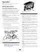
Operation Note: Determine the left and right sides of the machine from the normal operating position. Making Adjustments Adjusting the Bedknife to the Reel Use this procedure to set the bedknife to the reel and to check the condition of the reel and bedknife and their interaction. After completing this procedure, always test the cutting unit performance under your field conditions. You may need to make further adjustments to obtain optimal cutting performance. Figure 9 1. Cutting unit kickstand 4.
Note: Each click turned moves the bedknife 0.022 mm (0.0009 inch). Do not over tighten the adjusting screws. 12. Test the cutting performance by inserting a long strip of Toro cutting performance paper between reel and bedknife, perpendicular to the bedknife (Figure 10). 7. Verify that the bedknife-to-reel contact is correct. Tip the mower to expose the front and rear rollers and the bedknife.
Rear Spacers Height-of-Cut Chart Terms The number of rear spacers determines the aggressiveness of cut for the cutting unit. For a given height of cut, adding spacers, below the side plate mounting flange, increases the aggressiveness of the cutting unit. All cutting units on a given machine must be set to the same aggressiveness of cut (Number of rear spacers, part no. 106-3925), otherwise the after-cut appearance could be negatively affected (Figure 13).
Height-of-Cut Chart These are the recommended height-of- cut settings when a groomer kit is installed on the cutting unit. HOC Setting Aggressiveness of Cut No. of Rear Spacers No. of Chain Links With Groomer kits installed** 0.64 cm (0.250 inch) Less Normal More 0 0 1 5 5 5 Y Y - 0.95 cm (0.375 inch) Less Normal More 0 1 2 5 5 5 Y Y - 1.27 cm (0.500 inch) Less Normal More 0 1 2 5 5 5 Y Y Y 1.56 cm (0.625 inch) Less Normal More 1 2 3 5 5 5 Y Y - 1.91 cm (0.
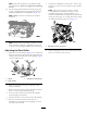
Adjusting the Height of Cut (HOC) Note: For heights of cut greater than 2.54 cm (1.00 inch) the High Height-of-Cut Kit must be installed. 1. Loosen the locknuts securing the height-of-cut arms to the cutting unit side plates (Figure 15). Figure 17 Figure 15 1. Adjusting screw 3. Height-of-cut arm 6. Adjust both ends of roller until entire roller is parallel to the bedknife. 2.
Use the following chart to determine which bedknife is best suited for the desired height of cut. Bedknife/Height-of-Cut Chart Bedknife Bedknife Lip Height Height of Cut EdgeMax® Low HOC (Model 03641) 5.6 mm (0.220 inch) 6.4-12.7 mm (0.250-0.500 inch) Low HOC (Optional) 5.6 mm (0.220 inch) 6.4-12.7 mm (0.250-0.500 inch) Extended EdgeMax® Low HOC (Optional) 5.6 mm (0.220 inch) 6.4-12.7 mm (0.250-0.500 inch) Extended Low HOC (Optional) 5.6 mm (0.220 inch) 6.4-12.7 mm (0.250-0.
The adjustment knobs have detentes corresponding to 0.022 mm (0.0009 inch) bedknife movement for each indexed position. If excessive contact/reel drag is evident it will be either necessary to backlap, reface the front of the bedknife, or regrind the cutting unit to achieve the sharp edges needed for precision cutting (Refer to the Toro Manual for Sharpening Reel and Rotary Mowers). Light contact is preferred at all times.
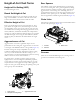
Maintenance Lubricating the Cutting Units Each cutting unit has 5 grease fittings (Figure 21) that must be lubricated regularly with #2 general-purpose, lithium-based grease. There are 2 lubrication points on the front roller, rear roller, and 1 at the reel motor spline. Note: Lubricating cutting units immediately after washing helps purge water out of the bearings and increases bearing life. 1. Wipe each grease fitting with a clean rag. 2.
Relief-Grinding the Reel the bedknife—check the reel to bedknife contact again after cutting 2 faiways, as any burrs will be removed, which may create improper reel to bedknife clearance and thus accelerate wear. The new reel has a land width of 1.3 to 1.5 mm (0.050 to 0.060 inch) and a 30 degree relief grind. When the land width gets larger than 3 mm (0.120 inch) wide, do the following: 1. Apply a 30 degree relief grind on all reel blades until the land width is 1.3 mm (0.
Servicing the Bedknife The bedknife service limits are listed in the following chart. Important: Operating the cutting unit with the bedknife below the service limit may result in poor after-cut appearance and reduce the structural integrity of the bedknife for impacts. Bedknife Service Limit Chart Bedknife Part Bedknife Lip Height * Service Limit * EdgeMax® Low HOC (Model 03641) 127-7132 5.6 mm (0.220 inch) 6.4-12.7 mm (0.250-0.500 inch) 10/5 Degrees Low HOC (Optional) 110-4084 5.6 mm (0.
Assembling the Bedbar Servicing the Bedbar 1. Install the bedbar, positioning the mounting ears between the washer and bedbar adjuster. Removing the Bedbar 2. Secure the bedbar to each side plate with the bedbar bolts (nuts on bolts) and the 6 washers. 1. Turn bedbar adjuster screws counterclockwise to back the bedknife away from the reel (Figure 26). Note: Position a nylon washer on each side of the side plate boss. Place a steel washer outside each of the nylon washers (Figure 28). 3.
Servicing the HD Dual Point Adjusters (DPA) 4. Install a wave washer onto the adjuster shaft and slide the adjuster shaft into the flange bushings in the cutting unit frame (Figure 30). 1. Remove all parts (refer to the Installation Instructions for the HD DPA Kit and to Figure 30). 5. Secure the adjuster shaft with a flat washer and locknut (Figure 30). 2. Apply Never Seize to the inside of the bushing area on cutting unit center frame (Figure 30). 6.
Servicing the Roller and outer seals to rebuild a roller. The Roller Rebuild Tool Kit includes all the tools and the installation instructions required to rebuild a roller with the roller rebuild kit. Refer to your Part’s Catalog or contact your Authorized Distributor for assistance. The roller Rebuild Kit and the Roller Rebuild Tool Kit (Figure 31) are available for servicing the roller. The Roller Rebuild Kit includes all the bearings, bearing nuts, inner seals Figure 31 1. Roller Rebuild Kit (Part No.
Notes: 20
Notes: 21
Declaration of Incorporation The Toro Company, 8111 Lyndale Ave. South, Bloomington, MN, USA declares that the following unit(s) conform(s) to the directives listed, when installed in accordance with the accompanying instructions onto certain Toro models as indicated on the relevant Declarations of Conformity. Model No. Serial No.
International Distributor List Distributor: Country: Phone Number: Distributor: Phone Number: 57 1 236 4079 Colombia Japan 81 3 3252 2285 Czech Republic 420 255 704 220 420 255 704 Slovakia 220 Argentina 54 11 4 821 9999 Russia 7 495 411 61 20 Ecuador 593 4 239 6970 Finland 358 987 00733 Agrolanc Kft Balama Prima Engineering Equip. B-Ray Corporation Hungary Hong Kong Korea 36 27 539 640 852 2155 2163 82 32 551 2076 Maquiver S.A. Maruyama Mfg. Co. Inc. Mountfield a.s.
Toro General Commercial Product Warranty A Two-Year Limited Warranty Conditions and Products Covered The Toro Company and its affiliate, Toro Warranty Company, pursuant to an agreement between them, jointly warrant your Toro Commercial product (“Product”) to be free from defects in materials or workmanship for two years or 1500 operational hours*, whichever occurs first. This warranty is applicable to all products with the exception of Aerators (refer to separate warranty statements for these products).