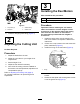
Form No. 3428-665 Rev A 8-Blade Radial Reel, 8-Blade Forward Swept Reel, or 11-Blade Forward Swept Reel EdgeSeries DPA Cutting Unit with 7in Reel Reelmaster® 5010 Series Traction Unit Model No. 03638—Serial No. 403450001 and Up Model No. 03639—Serial No. 403450001 and Up Model No. 03641—Serial No. 403450001 and Up Register at www.Toro.com.
This product complies with all relevant European directives. For details, please see the Declaration of Incorporation (DOI) at the back of this publication. Model No. Serial No. This manual identifies potential hazards and has safety messages identified by the safety-alert symbol (Figure 2), which signals a hazard that may cause serious injury or death if you do not follow the recommended precautions.
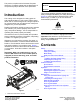
Safety Improperly using or maintaining this machine can result in injury. To reduce the potential for injury, comply with these safety instructions and always pay attention to the safety-alert symbol , which means Caution, Warning, or Danger—personal safety instruction. Failure to comply with these instructions may result in personal injury or death. This machine has been designed in accordance with EN ISO 5395 and ANSI B71.4–2017. General Safety This product is capable of amputating hands and feet.
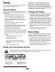
Setup Loose Parts Use the chart below to verify that all parts have been shipped. Procedure 1 2 3 Description Use Qty. Straight grease fitting 1 Install the reel grease fitting. No parts required – Adjust the cutting unit O-ring Cap screws (may come assembled) 1 2 Install the reel motors. Media and Additional Parts Description Qty.
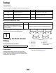
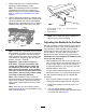
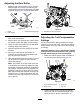
3 Installing the Reel Motors Parts needed for this procedure: g028640 3. Grease fitting 2. Setscrew 4. Grease vent 2. O-ring 2 Cap screws (may come assembled) Procedure Figure 4 1. Cap screw (2) 1 Important: Before installing the reel motors, obtain and install the counter weights or other accessories on the opposite side of the cutting units from the reel motors as described in the instructions provided with the weights or accessories. Install the straight grease fitting (Figure 4).
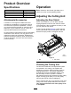
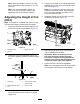
Product Overview Operation Specifications Cutting Unit Weight 03638 54 kg (118 lb) 03639 54 kg (118 lb) 03641 55 kg (121 lb) Note: Determine the left and right sides of the machine from the normal operating position. Adjusting the Cutting Unit Attachments/Accessories Adjusting the Rear Shield A selection of Toro approved attachments and accessories is available for use with the machine to enhance and expand its capabilities.
1. Slowly rotate the reel in a reverse direction, listening for reel-to-bedknife contact. Note: The adjustment knobs have detents corresponding to 0.023 mm (0.0009 inch) bedknife movement for each indexed position. Refer to Adjusting the Bedknife to the Reel (page 7). 2. Test the cutting performance by inserting a long strip of cutting performance paper (Toro Part No. 125-5610) between the reel and the bedknife, perpendicular to the bedknife (Figure 7).
Note: If starting with a large gap, both sides should initially be drawn closer by alternately tightening the right and left sides. 7. Slowly rotate the reel so that the same blade that you checked on the right side is crossing the bedknife approximately 25 mm (1 inch) in from the end of the bedknife on the left side of the cutting unit. 8. Turn the left bedbar adjuster clockwise until the shim can be slid through the reel to bedknife gap with light drag. 9.
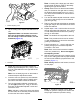
Adjusting the Rear Roller 1. Adjust the rear roller brackets (Figure 12) to the desired height-of-cut range by positioning the required amount of spacers below the side-plate mounting flange (Figure 12) per the HOC Chart. g003324 g027167 Figure 12 1. Spacer Figure 13 3. Side-plate mounting flange 1. Side-plate mounting cap screws 2. Roller bracket 2. Raise the rear of the cutting unit and place a block under the bedknife. 3.
Note: When operating the machine on rough 4. terrain, decrease the spring length by 12.7 mm (1/2 inch). Hook the screw head on the cutting edge of the bedknife and rest the rear end of the bar on the rear roller (Figure 17). Note: For checking the HOC on cutting units installed with shoulder rollers, place the gauge bar on the larger diameter shoulders on the ends of the shoulder roller.
Height-of-Cut Chart HOC Setting Aggressiveness of Cut No. of Rear Spacers No. of Chain Links With Groomer kits installed** 0.64 cm (0.250 inch) Less Normal More 0 0 1 5 5 5 Y Y - 0.95 cm (0.375 inch) Less Normal More 0 1 2 5 5 5 Y Y - 1.27 cm (0.500 inch) Less Normal More 0 1 2 5 5 5 Y Y Y 1.56 cm (0.625 inch) Less Normal More 1 2 3 5 5 5 Y Y - 1.91 cm (0.750 inch) Less Normal More 2 3 4 5 5 5 Y Y - 2.22 cm (0.875 inch) Less Normal More 2 3 4 5 5 5 Y Y - 2.54 cm (1.
Use the following chart to determine which bedknife is best suited for the desired height of cut. Bedknife/Height of Cut Chart Bedknife Part No. Bedknife Lip Height Height of Cut Low HOC (Optional) 110-4084 5.6 mm (0.220 inch) 6.4 to 12.7 mm (0.250 to 0.500 inch) EdgeMax® Low HOC (Model 03641) 137-0832 5.6 mm (0.220 inch) 6.4 to 12.7 mm (0.250 to 0.500 inch) Extended Low HOC (Optional) 120-1640 5.6 mm (0.220 inch) 6.4 to 12.7 mm (0.250 to 0.
Rear Spacers The number of rear spacers determines the aggressiveness of cut for the cutting unit. For a given height of cut, adding spacers below the side-plate mounting flange increases the aggressiveness of the cutting unit. All cutting units on a given machine must be set to the same aggressiveness of cut (number of rear spacers, Toro Part No. 106-3925); otherwise, the after-cut appearance could be negatively affected (Figure 19).
Maintenance Using the Kickstand When Tipping the Cutting Unit Whenever the cutting unit has to be tipped to expose the bedknife/reel, prop up the rear of the cutting unit with the kickstand (supplied with the traction unit) to make sure that the nuts on the back end of the bedbar adjusting screws are not resting on the work surface (Figure 21). g027174 Figure 22 Grease fitting locations on the reel motor side. Relief-Grinding the Reel The new reel has a land width of 1.3 to 1.5 mm (0.050 to 0.
g028838 Figure 24 Models 03639 and 03641 1. 1.3 mm (0.050 inch) 2. 2. 30 degrees Spin grind the reel to achieve <0.025 mm (0.001 inch) reel run-out. Note: This causes the land width to grow slightly. Note: To extend the longevity of the sharpness of the edge of the reel and the bedknife—after grinding the reel and/or the bedknife—check the reel to bedknife contact again after cutting 2 faiways, as any burrs will be removed, which may create improper reel to bedknife clearance and thus accelerate wear.
Servicing the Bedknife The bedknife service limits are listed in the following chart. Important: Operating the cutting unit with the bedknife below the service limit may result in poor after-cut appearance and reduce the structural integrity of the bedknife for impacts. Bedknife Service Limit Chart Bedknife Part Bedknife Lip Height * Service Limit * EdgeMax® Low HOC (Model 03641) 137-0832 5.6 mm (0.220 inch) 6.4-12.7 mm (0.250-0.500 inch) 10/5 Degrees Low HOC (Optional) 110-4084 5.6 mm (0.
Servicing the Bedbar Removing the Bedbar 1. Turn the bedbar-adjusting screws counterclockwise to back the bedknife away from the reel (Figure 29). g034113 Figure 27 2. Angle indicator 1. Bedknife (vertical) 2. Press the Alt Zero button on the angle indicator. 3. Place the angle-indicator mount on the edge of the bedknife so that the edge of the magnet mates with the edge of the bedknife (Figure 28).
g027176 Figure 31 1. Bedbar bolt 2. Nut 3. Steel washer 4. Nylon washer Assembling the Bedbar 1. Install the bedbar, positioning the mounting ears between the washer and bedbar adjuster. 2. Secure the bedbar to each side plate with the bedbar bolts (nuts on bolts) and the 6 washers. g279161 Note: Position a nylon washer on each side Figure 33 of the side-plate boss. Place a steel washer outside each of the nylon washers (Figure 31). 3. 1. Bedbar 2.
Servicing the HD Dual Point Adjusters (DPA) 1. 2. 3. Remove all parts (refer to the Installation Instructions for the HD DPA Kit and to Figure 35). Apply anti-seize compound to the inside of the bushing area on cutting unit center frame (Figure 35). Align the keys on flange bushings to the slots in the frame and install the bushings (Figure 35). 4. Install a wave washer onto the adjuster shaft and slide the adjuster shaft into the flange bushings in the frame of the cutting unit (Figure 35). 5.
16. Repeat this procedure on the other end of the cutting unit. 17. Adjust the bedknife to the reel; refer to Adjusting the Bedknife to the Reel (page 7). Roller Rebuild Kit includes all the bearings, bearing nuts, inner seals and outer seals to rebuild a roller. The Roller Rebuild Tool Kit includes all the tools and the installation instructions required to rebuild a roller with the roller rebuild kit. Refer to your Parts Catalog or contact your Authorized Distributor for assistance.
Notes:
Declaration of Incorporation The Toro Company, 8111 Lyndale Ave. South, Bloomington, MN, USA declares that the following unit(s) conform(s) to the directives listed, when installed in accordance with the accompanying instructions onto certain Toro models as indicated on the relevant Declarations of Conformity. Model No. Serial No.
EEA/UK Privacy Notice Toro’s Use of Your Personal Information The Toro Company (“Toro”) respects your privacy. When you purchase our products, we may collect certain personal information about you, either directly from you or through your local Toro company or dealer.
The Toro Warranty Two-Year or 1,500 Hours Limited Warranty Conditions and Products Covered Parts The Toro Company and its affiliate, Toro Warranty Company, pursuant to an agreement between them, jointly warrant your Toro Commercial product (“Product”) to be free from defects in materials or workmanship for 2 years or 1,500 operational hours*, whichever occurs first. This warranty is applicable to all products with the exception of Aerators (refer to separate warranty statements for these products).