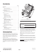
Form No. 3354–704 Rev. D 8 Blade DPA Cutting Unit with 5 inch Reel Reelmaster) 5210 & 5410 Traction Units Model No. 03661—Serial No.
Contents Introduction . . . . . . . . . . . . . . . . . . . . . . . . . . . . . . . . Safety . . . . . . . . . . . . . . . . . . . . . . . . . . . . . . . . . . . . . Safe Operating Practices . . . . . . . . . . . . . . . . . . . . Safety and Instruction Decals . . . . . . . . . . . . . . . . Specifications . . . . . . . . . . . . . . . . . . . . . . . . . . . . . . . General Specifications . . . . . . . . . . . . . . . . . . . . . Cutting Unit Accessories and Kits . . . . . . . . . . . . Setup . . . . . .
Safety • Remove all debris or other objects that might be picked up and thrown by the cutting unit reel blades. Keep all bystanders away from the working area. Safe Operating Practices • If the cutting blades strike a solid object or the unit vibrates abnormally, stop and shut the engine off. Check cutting unit for damaged parts. Repair any damage before restarting and operating the cutting unit.
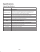
Specifications General Specifications Tractors Height of Cut These cutting units will mount on the Reelmaster® 5210 & 5410 Traction Units. Cutting height is adjusted on the front roller by two vertical screws and held by two locking capscrews. Height Of Cut Range Standard bench height of cut range is .250 inch (3 mm) to 1.00 inch (25 mm). Bench height of cut range with the High Height of Cut Kit installed is 1.00 inch (25 mm) to 1.50 inches (38 mm).
Cutting Unit Accessories and Kits (see parts catalog for part numbers) Short Rear Roller: Helps reduce double roller marks for cool season grasses (Bent, Blue grass, Rye). Note: All accessories and kits are 1 per cutting unit unless otherwise specified. Full Front Roller: Helps produce more pronounced striping (repeated cutting in the same direction/path), however, effective height of cut is raised and quality of cut is reduced.
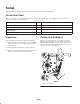
Setup Note: Determine the left and right sides of the machine from the normal operating position. Loose Parts Chart Note: Use this chart as a checklist to ensure all parts necessary for assembly have been shipped. If any of these parts are missing, total setup cannot be completed. Description Qty. Use O–ring 1 Install on reel motor. Operator’s manual 1 Read before operating the machine.
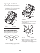
Adjusting the Rear Shield Under most conditions, best dispersion is attained when the rear shield is closed (front discharge). When conditions are heavy or wet, rear shield may be opened. 1. To open the rear shield (Fig. 3), loosen the capscrew securing the shield to the left side plate, rotate the shield to the open position and tighten the capscrew. Figure 5 1. Counter weight 2. On right end of cutting unit, remove plastic plug from bearing housing (Fig. 6). 3.
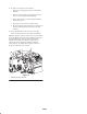
Adjustments Use the following procedures to ensure that the cutting units are adjusted properly. Adjusting the Bedknife to the Reel Bedknife to reel adjustment is accomplished by loosening or tightening bedbar adjusting screws, located on top of mower. Figure 8 1. Position machine on a flat, level work surface. Make sure reel contact is removed by turning bedbar adjusting screws counterclockwise (Fig. 7). 4. Check for light contact at other end of reel using paper and adjust as required. 5.
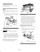
2. To adjust rear roller proceed as follows: • Raise rear of cutting unit and place a block under bedknife. • Remove (2) nuts securing each roller bracket and spacer to each sideplate mounting flange. • Lower roller and screws from sideplate mounting flanges and spacers. • Place spacers onto screws on roller brackets. • Re–secure roller bracket and spacers to underside of sideplate mounting flanges with nuts previously removed. 3. Verify that bedknife to reel contact is correct.
Height of Cut Chart Terms Rear Spacers The number of rear spacers determines the aggressiveness of cut for the cutting unit. For a given height of cut, adding spacers, below the sideplate mounting flange, increases the aggressiveness of the cutting unit. All cutting units on a given machine must be set to the same aggressiveness of cut (Number of rear spacers, part no. 106–3925), otherwise the after-cut appearance could be negatively affected (Fig. 11).
Height of Cut Chart Height of Cut Setting (HOC) Aggressiveness of Cut Number of Rear Spacers Number of Chain Links With Groomer Kits installed 0.250” Less Normal More 0 0 1 3+ 3+ 3 Y Y – 0.375” Less Normal More 0 1 2 4 3 3 Y Y – 0.500” Less Normal More 0 1 2 4 3+ 3 Y Y Y 0.625” Less Normal More 1 2 3 4 3 3 Y Y – 0.750” Less Normal More 2 3 4 3+ 3 3 Y Y – 0.875” Less Normal More 2 3 4 4 3 3 Y Y – 1.000” Less Normal More 3 4 5 3+ 3 3 Y Y – 1.
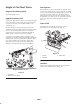
Adjusting the Height of Cut Note: For heights of cut greater than 1.00” the High Height of Cut Kit must be installed. 1. Loosen locknuts securing height-of-cut arms to cutting unit side plates (Fig. 13). Figure 15 Figure 13 1. Height-of-cut arm 2. Locknut Important When set properly, the rear and front rollers will contact the gauge bar and the screw will be snug against the bedknife. This ensures that the height-of-cut is identical at both ends of the bedknife. 3. Adjusting screw 5.
Operation Note: Over time, the chamfer (Fig. 16) will need to be reground as it is only designed to last 40% of the bedknife life. Note: Determine the left and right sides of the machine from the normal operating position. Cutting Unit Characteristics The dual knob bedknife-to-reel adjustment system incorporated in this cutting unit simplifies the adjustment procedure needed to deliver optimum mowing performance.
Maintenance Note: Determine the left and right sides of the machine from the normal operating position. Lubrication Each cutting unit has (6) grease fittings (Fig. 17) that must be lubricated regularly with No. 2 General Purpose Lithium Base Grease. Figure 18 1. Bedknife adjusting knob The lubrication points are front roller (2), rear roller (2) and reel bearing (2) 2. Using a rag or thickly padded glove, hold on to the reel blade and try to move the reel assembly side to side (Fig. 19).
B. Using a 1–3/8” socket wrench, slowly tighten the reel bearing adjustment nut until no end play of the reel exists. If adjusting nut does not eliminate reel end play, replace reel bearings. Note: Reel bearings do not require pre–load. Over tightening reel bearing adjuster nut will damage reel bearings. 4. Retighten set screw securing bearing adjusting nut to bearing housing. Torque to 12–15 in–lbs. Servicing the Bedbar Removing the Bedbar 1.
The Toro General Commercial Products Warranty A Two-Year Limited Warranty Conditions and Products Covered The Toro Company and its affiliate, Toro Warranty Company, pursuant to an agreement between them, jointly warrant your Toro Commercial Product (“Product”) to be free from defects in materials or workmanship for two years or 1500 operational hours*, whichever occurs first.