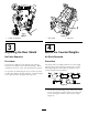
Form No. 3362-857 Rev B 8 and 11 Blade DPA Cutting Units with 5 inch Reels Reelmaster® 5210 & 5410 Traction Units Model No. 03661—Serial No. 310000001 and Up Model No. 03695—Serial No. 310000001 and Up To register your product or download an Operator's Manual or Parts Catalog at no charge, go to www.Toro.com.
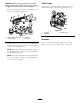
Introduction Figure 2 Read this information carefully to learn how to operate and maintain your product properly and to avoid injury and product damage. You are responsible for operating the product properly and safely. 1. Safety alert symbol This manual uses 2 other words to highlight information. Important calls attention to special mechanical information and Note emphasizes general information worthy of special attention. You may contact Toro directly at www.Toro.
Safety Wearing safety glasses, safety shoes and a helmet is advisable and required by some local ordinances and insurance regulations. Hazard control and accident prevention are dependent upon the awareness, concern, and proper training of the personnel involved in the operation, transport, maintenance, and storage of the machine. Improper use or maintenance of the machine can result in injury or death. To reduce the potential for injury or death, comply with the following safety instructions.
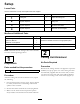
Setup Loose Parts Use the chart below to verify that all parts have been shipped. Procedure Description 1 2 3 4 Use Qty. Cutting unit 1 Inspect the cutting unit No parts required – Use the kickstand when tipping the cutting unit No parts required – Adjust the rear shield No parts required – Mount the counter weights Media and Additional Parts Description Use Qty.
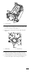
Figure 3 Figure 4 1. Cutting unit kickstand 1. Rear shield 3 2. Cap screw 4 Adjusting the Rear Shield Mount the Counter Weights No Parts Required No Parts Required Procedure Procedure Under most conditions, best dispersion is attained when the rear shield is closed (front discharge). When conditions are heavy or wet, rear shield may be opened. All cutting units are shipped with the counter weight mounted to the left end of the cutting unit.
Figure 6 1. Counter weight 2. On right end of cutting unit, remove the plastic plug from the bearing housing (Figure 7). 3. Remove the 2 cap screws from the right side plate (Figure 7). 1 G003321 2 Figure 7 1. Plastic plug 2. Cap screw (2) 4. Install the counter weight to the right end of the cutting unit with the 2 screws previously removed. 5. Loosely install the 2 reel motor mounting cap screws to the left side plate of the cutting unit (Figure 7).
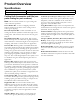
Product Overview Specifications Net Weight Model 03661-112 lb. (51 kg) Model 03695-116 lb. (52 kg) Cutting Unit Accessories and Kits (see parts catalog for part numbers) Collar Kit (6 needed per roller): Helps reduce over lap marks for warm season grasses (Bermuda, Zoysia, Paspalum). This kit is installed on the outer three grooves of the existing Wiehle roller, but is not as aggressive as the Shoulder roller.
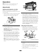
Operation Note: Determine the left and right sides of the machine from the normal operating position. Adjustments Adjusting the Bedknife to the Reel G003323 Bedknife to reel adjustment is accomplished by loosening or tightening bedbar adjusting screws, located on top of mower. Figure 9 4. Check for light contact at other end of reel using paper and adjust as required. 5.
Aggressiveness of Cut 6. Re-secure roller bracket and spacers to underside of side plate mounting flanges with nuts previously removed. Cutting unit Aggressiveness of Cut has a significant impact on the performance of the cutting unit. Aggressiveness of Cut refers to the angle of the bedknife relative to the ground (Figure 12). 7. Verify that bedknife to reel contact is correct. Tip mower to expose front and rear rollers and bedknife.
Chain Links Important: Make spring adjustments with the cutting unit mounted to the traction unit, pointing straight ahead and lowered to the shop floor. The location at which the lift arm chain is attached determines the rear roller pitch angle (Figure 14). 1. Make sure the hairpin cotter is installed in the rear hole in the spring rod (Figure 13). Figure 14 1. Lift chain 2. U-Bracket 3. Bottom hole Figure 13 1. Turf compensation spring 2. Hair pin cotter 3. Spring rod 4.
Height of Cut Chart HOC Setting Aggressiveness of Cut No. of Rear Spacers No. of Chain Links With Groomer kits installed 0.250 inch (6 mm) Less Normal More 0 0 1 3+ 3+ 3 Y Y - 0.375 inch (9 mm) Less Normal More 0 1 2 4 3 3 Y Y - 0.500 inch (13 mm) Less Normal More 0 1 2 4 3+ 3 Y Y Y 0.625 inch (16 mm) Less Normal More 1 2 3 4 3 3 Y Y - 0.750 inch (19 mm) Less Normal More 2 3 4 3+ 3 3 Y Y - 0.875 inch (22 mm) Less Normal More 2 3 4 4 3 3 Y Y - 1.
Adjusting the Height of Cut Note: For heights of cut greater than 1.00 inch the High Height of Cut Kit must be installed. 1. Loosen locknuts securing height-of-cut brackets to cutting unit side plates (Figure 15). Figure 17 Figure 15 Important: When set properly, the rear and front rollers will contact the gauge bar and the screw will be snug against the bedknife. This ensures that the height-of-cut is identical at both ends of the bedknife. 3. Adjusting screw 1. Height-of-cut bracket 2. Locknut 2.
cutting edge surface along the full length of the bedknife. If a file is occasionally run across the front edge to remove this burr, improved cutting can be obtained. After extended running, a ridge will eventually develop at both ends of the bedknife. These notches must be rounded off or filed flush with the cutting edge of the bedknife to ensure smooth operation. Figure 18 1.
Servicing Bedknife The bedknife service limits are listed in the following charts. Important: Operating the cutting unit with the bedknife below the “service limit” may result in poor after-cut appearance and reduce the structural integrity of the bedknife for impacts. Bedknife Service Limit Chart Bedknife Part No. Low HOC (Optional) 110-4084 Extended Low HOC (Optional) Bedknife Lip Height * .220 inch (5.6 mm) Service Limit * .190 inch (4.8 mm) 120–1640 .220 inch (5.6 mm) .190 inch (4.
Maintenance Lubrication Each cutting unit has (6) grease fittings (Figure 22) that must be lubricated regularly with No. 2 General Purpose Lithium Base Grease. Figure 23 The lubrication points are front roller (2), rear roller (2) and reel bearing (2). 1. Bedknife adjusting knob Note: Lubricating cutting units immediately after washing helps purge water out of bearings and increases bearing life. 2.
Note: Reel bearings do not require preload. Over tightening reel bearing adjuster nut will damage reel bearings. 4. Retighten set screw securing bearing adjusting nut to bearing housing. Torque to 12-15 in-lb (1.4-1.7 N-m). Servicing the Bedbar Removing the Bedbar 1. Turn bedbar adjuster screws, counterclockwise, to back bedknife away from reel (Figure 26). Figure 28 1. Bedbar bolt 2. Nut 3. Steel washer 4. Nylon washer Assembling the Bedbar 1.
Servicing the Roller inner seals and outer seals to rebuild a roller. The Roller Rebuild Tool Kit includes all the tools and the installation instructions required to rebuild a roller with the roller rebuild kit. Refer to your parts catalog or contact your distributor for assistance. A Roller Rebuild Kit, Part No. 114–5430 and a Roller Rebuild Tool Kit, Part No. 115–0803 (Figure 30) are available for servicing the roller. The Roller Rebuild Kit includes all the bearings, bearing nuts, Figure 30 1. 2. 3.
Notes: 18
Notes: 19
The Toro Total Coverage Guarantee A Limited Warranty Conditions and Products Covered The Toro® Company and its affiliate, Toro Warranty Company, pursuant to an agreement between them, jointly warrant your Toro Commercial product (“Product”) to be free from defects in materials or workmanship for two years or 1500 operational hours*, whichever occurs first. This warranty is applicable to all products with the exception of Aerators (refer to separate warranty statements for these products).