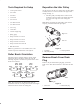
Form No. 3358–465 Rev B Rear Roller Brush Kit Reelmaster 5210/5410 Series Cutting Unit with 5 in. Reels Model No. 03663 Reelmaster 5510/5610 Series Cutting Unit with 7 in. Reels Reelmaster 6500/6700 Series DPA Cutting Unit with 7 in. Reels Model No.
Contents Introduction Page Introduction . . . . . . . . . . . . . . . . . . . . . . . . . . . . . . . . Safety . . . . . . . . . . . . . . . . . . . . . . . . . . . . . . . . . . . . . Safe Operating Practices . . . . . . . . . . . . . . . . . . . Setup . . . . . . . . . . . . . . . . . . . . . . . . . . . . . . . . . . . . . Loose Parts . . . . . . . . . . . . . . . . . . . . . . . . . . . . . . Tools Required for Setup . . . . . . . . . . . . . . . . . . . Roller Brush Orientation . . . . . . . . . . .
Safety • Remove all debris or other objects that might be picked up and thrown by the cutting unit blades. Keep all bystanders away from the mowing area. Safe Operating Practices • If the blades strike a solid object or the cutting unit vibrates abnormally, stop and shut the engine off. Check cutting unit for damaged parts. Repair any damage before restarting and operating the cutting unit.
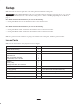
Setup Note: Determine the left and right sides of the cutting unit from behind the cutting unit. Important The Rear Roller Brush Kit is only to be used when cutting in the height of cut range of 1/4” to 1”. Use the High Height of Cut Brush, Part No. 110–1740 when cutting above 1”. Refer to Installing High Height of Cut Brush on page 7. Rear Roller Brush Kit Model 03663 may be used on the following: • Cutting Unit Model 03661 for the Reelmaster 5210 or 5410 Traction Units.
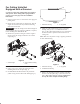
Tools Required for Setup Reposition the Idler Pulley • 1/2 deep–well socket On the left front and left rear cutting units, the idler pulley assembly must be reversed to mount on the right end of cutting unit (Fig. 2). • 9/16 socket • 5/8 socket • The idler pulley assembly must be removed and mounted to the lower hole in the brush plate when it is used on the right end of the cutting unit (Fig. 2).
For Cutting Units Not Equipped with a Groomer 2 1 Use this procedure if the cutting unit is not equipped with groomer. If the cutting unit is equipped with a groomer, proceed to page 10 for the installation instructions. 1. Park the traction unit on a level surface and engage the parking brake. Figure 5 2. Ensure that the cutting units are disengaged. Turn the engine off and remove the key. Remove all cutting units from traction unit. 1. Roller brush housing 2. O–ring (yellow) 6.
brackets and the side plate mounting flanges. Install additional 1/4 inch spacers on the top side of the roller brush mounting bracket (Fig. 9). 1 1 2 3 Figure 7 1. Remove nuts securing each end of roller 2 2. 1/4” spacer 3. Side plate mounting flange 3 8. Position the roller brush assembly mounting brackets onto the roller bracket capscrews (Fig. 8). Secure the brush assembly mounting brackets to the cutting unit side plates with the nuts previously removed. Figure 9 1.
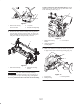
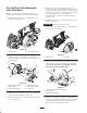
15. Apply 242 Loctite (blue) to the shoulder bolt (Fig. 11). Mount the brush plate to the roller brush housing with the shoulder bolt. (Fig. 11). Torque the bolt to 15–19 ft–lb. 10. Apply a coating of grease to the inner diameter of the grommet in the bearing housing (Fig. 11). 6 5 7 16. Insert the spacer onto the shaft in the bearing housing (Fig. 12). 3 17. Insert the drive pulley into the spacer and onto the drive shaft (Fig. 12).
Note: Refer to the decal on the inside of the belt cover for belt tightening information. Figure 14 1 Figure 16 21. Check the alignment of the belt/pulleys as follows: 1. Belt cover • The belt must be properly tensioned prior to checking alignment. 23. Lubricate the grease fittings on each of the roller brush bearing housings and on the remainder of the cutting unit with No. 2 General Purpose Lithium Base Grease (Fig. 17). Wipe off any excess grease, specifically around the excluder seals.
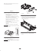
For Cutting Units Equipped with Groomers 5. Remove the set screw from the center hole in the groomer cover (Fig. 19). Install this set screw and the set screw included with the Groomer kit, into the holes previously used for the cover mounting screws. Apply 242 Loctite (blue) to the set screws prior to installation. The set screws are to be flush with the groomer cover. Note: If a groomer kit and a brush kit are going to be installed on the cutting unit, install the groomer kit first. 1.
2 1 1 3 Figure 24 1. Excluder seal 2. Bearing housing Figure 22 3. Mounting bracket 11. Loosen but do not remove the bolts securing the roller brush bearing housing to the roller brush mounting bracket (Fig. 25). 1. Roller brush assembly Important The roller brush assembly mounting brackets must be mounted directly to the top surface of the cutting unit side plate mounting flange. No spacers are to be positioned between the roller brush mounting brackets and the side plate mounting flanges.
14. Check to make sure the roller brush plate is parallel to the cutting unit side plate. If it is not parallel, proceed as follows: 19. Install the belt onto the pulleys (Fig. 26 & 28). Make sure the ribs on the belt are properly seated in the grooves in each pulley. • Loosen the (2) flange locknuts securing the roller brush mounting bracket to the cutting unit side plate (Fig. 25). 20. With the idler pulley nut loose, use a spring gauge to pull up on the idler plate tab with 15 lbs.
Figure 29 Figure 31 • The outer faces of the drive and driven pulleys should be in line within .030 inch. 24. Adjust the brush. Refer to Adjusting the Brush, page 15. • If the pulleys are not aligned, Refer to the section on Pulley Alignment. • If the pulleys are aligned, continue with the installation. Installing the High Height of Cut Brush (optional) • Do Not use the idler pulley to check alignment. Important The belt may fail prematurely if the pulleys are not properly aligned.
Maintenance 1. Clean under the belt cover and check the every 50 hours. 2 1 2. Make sure the brush is parallel to the roller with .060 inch clearance to light contact. 3. Grease fittings every 50 hours or after every washing. 3 4. When replacing roller brush, torque J bolts to 20 to 25 in–lbs. 5. When replacing the brush shaft driven pulley, torque the nut to 27–33 ft–lb. Figure 33 1. Non–drive bearing housing 2. Excluder seal 3. Brush shaft 6.
5. If the pulley needs to move out, add one .032 thick spacer (Fig. 36). If the pulley needs to move in, remove the existing .032 thick spacer . 6. Re–install the pulley. 4 1 1 3 Figure 38 3 1. Loosen these bolts 2 2. Position the roller brush so it is in light contact with the rear roller (Fig. 39). Figure 36 1. Lock nut 2. Driven pulley 3. Spacer (.032 thick) 4. Brush shaft flats Important The roller brush shaft must not contact the cutting unit sideplate. 1 7.