Form No. 3391-931 Rev A Right/Left Hand Groomer Kit Reelmaster® 5210/5410 Series Cutting Unit with 5in Reel or Reelmaster® 5510/5610/6500/6700 Series Cutting Unit with 7in Reel Model Model Model Model Register at www.Toro.com. Original Instructions (EN) No. No. No. No.
This manual uses 2 words to highlight information. Important calls attention to special mechanical information and Note emphasizes general information worthy of special attention. WARNING CALIFORNIA Proposition 65 Warning This product contains a chemical or chemicals known to the State of California to cause cancer, birth defects, or reproductive harm. This product complies with all relevant European directives. For details, please see the Declaration of Incorporation (DOI) at the back of this publication.
Contents Safety Safety ........................................................................... 3 Safe Operating Practices........................................... 3 Setup ............................................................................ 5 Tools Required for Setup .......................................... 5 Installing the Groomer............................................. 6 Installing the Broomer Kit (Optional)........................16 Operation ........................................
genuineness. Using unapproved replacement parts and accessories could void the warranty of The Toro® Company.
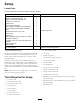
Setup Loose Parts Use the chart below to verify that all parts have been shipped. Description Use Qty. 45 degree grease fitting Height of cut bracket assembly, R.H. Height of cut bracket assembly, L.H.
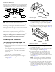
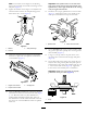
Groomer Kit Orientation All cutting units are shipped with the counter weight mounted to the left end of the cutting unit. Use the following diagram to determine the position of the groomer kits and reel motors. Figure 3 Figure 2 * For Reelmaster 6700 only 1. Counter weight 2. Grease fitting 4. Remove the straight grease fitting from the bearing housing and replace with the 45 degree fitting (Figure 3). Position the fitting so it points to the top of the cutting unit.
Important: The splined insert on the left hand side of the cutting unit has left hand threads. The splined insert, on the right hand side of the cutting unit, has right hand threads. Note: The washers on the height of cut adjusting bolts must be located on each side of the flange on the side plate (Figure 5). 10. Tighten the locknut on the height of cut adjuster bolt until the washers contact the side plate flange, then back-off the nut 1/2 turn (Figure 5). 13.
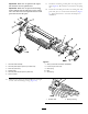
Important: Make sure the splined end of pivot hub shaft fits into the splined insert. 17. Install the non-drive groomer plate onto the groomer shaft (Figure 9). Be careful not to knock the seal spring off. Important: Make sure the pivot hub mounting surface is flush with the side plate on the cutting unit. The shim must not be pinched between the pivot hub and the side plate. 18. Secure the non-drive pivot hub to the cutting unit side plate with (2) 3/8 x 1 inch socket head screws (Figure 9).
20. Mount the quick-up lever assemblies to the side plates with 3/8 x 3/4 inch flange head bolts (Figure 9). • The outer faces of the drive and driven pulleys 21. Install the groomer belt onto the pulleys (Figure 9). Make sure the ribs on the belt are properly seated in the grooves on each pulley. • • 22. Hook the idler spring in the hole in the idler plate tab and around the groove on the groomer plate lower stud (Figure 11). The open end of the spring hook is to be positioned toward the drive pulley.
Note: After greasing groomer bearings, operate groomer for 30 seconds, stop machine and wipe excess grease from groomer shaft and seals. idler pulley to the roller brush pivot plate. Do not remove the nut. 5. Remove the bolt securing the roller brush drive pulley to the bearing housing shaft (Figure 16). 27. Adjust the height of the groomer. Refer to Adjusting Groomer Height. 6. Remove the roller brush drive pulley and the spacer from the shaft (Figure 16).
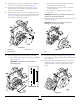
Figure 20 Figure 18 1. Height of cut bracket 1. Bearing housing 3. Carriage bolt 2. Capscrew and locknut 12. Remove the carriage bolts and nuts securing the height of cut brackets to the cutting unit side plates (Figure 19). 16. Using the upper square hole in each side plate, loosely mount the height of cut brackets to the cutting unit side plates with the carriage bolts previously removed and new 3/8 inch flange nuts, positioning as shown in figure Figure 20. 13.
23. On the drive side of the cutting unit, mount the pivot hub, the drive side groomer plate and the shim to the cutting unit side plate with (2) 3/8 x 1 inch socket head screws (Figure 24). Apply blue Loctite to the screw threads prior to installation. models 03665 and 03666 and reel drive shaft tool, Part TOR4074 on models 03685 and 03686. Clean all the grease out of the threaded hole where the splined insert was.
Figure 25 1. Excluder seal 2. Bearing housing 27. Mount the quick-up lever assemblies to the side plates with 3/8 x 3/4 inch flange head bolts (Figure 24). Figure 27 28. Install the groomer belt onto the pulleys (Figure 24). Make sure the ribs on the belt are properly seated in the grooves on each pulley. • The outer faces of the drive and driven pulleys should be in line within .030 inch. 29.
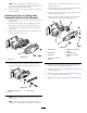
6 34. Remove the set screw from the center hole in the groomer cover (Figure 28). Install this set screw and the set screw, included with the kit, into the holes previously used for the cover mounting screws. Apply Loctite to the setscrews prior to installation. Make sure the set screws are flush with the cover. 5 7 G011426 4 35. Install the groomer cover and secure with (2) 5/16 inch flange nuts (Figure 29). Important: Do not over tighten the nuts. 2 1 3 Figure 30 1. Shoulder bolt 2.
Important: Not using a spring gauge to set the belt tension may cause premature belt failure. Note: Refer to the decal on the inside of the belt cover for belt tightening information. G011427 1 Figure 33 3 2 Figure 31 1. Groomer pulley mounting bolt (remove) 3. Belt 2. Drive pulley 45. Install the belt onto the pulleys and spring loaded idler as follows: • Loop the belt around the driven pulley and then over the top of the idler pulley (Figure 32). Figure 34 1. Brush plate tab 2.
Important: Do not overtighten nuts as damage to cover may occur. Figure 38 Figure 36 1. Brush 2. Strap 1. Belt cover 2. Verify that the brushes are seated in the groomer blade slots (Figure 39 and Figure 40). 49. Fill each reel bearing housing with grease (Figure 37). Excess grease will purge between the inboard seals and the seal guards. 3.
Operation Grooming is performed in the turf canopy above the soil level. Grooming promotes vertical growth of grass plants, reduces grain and severs stolons producing a denser turf. Grooming produces a more uniform and tighter playing surface for faster and truer action of the golf ball. Verticutting is a more aggressive cultivation technique designed to remove thatch by cutting through the turf canopy and into the thatch/mat layer. Grooming should not be considered a replacement for verticutting.
• The type of grass • The overall management program (i.e. irrigation, fertilizing, spraying, coring, over seeding, etc.) • The traffic on the fairway • Stress periods (i.e., high temperatures, high humidity, unusually high traffic) These factors can vary from golf course to golf course. It is important, therefore, to inspect the fairways frequently and vary the grooming practice in accordance with the need.
Height of Cut (HOC) and Height of Groom (HOG) Recommended Range Height of Cut Number of Rear Roller Spacers Recommended HOG = HOC- Groomer Engagement .250 0 .125-.250 .375 .375 0 1 .187-.375 .187-.375 .500 .500 .500 0 1 2 .250-.500 .250-.500 .250-.375 .625 .625 .625 0 1 2 .375-.625 .375-.625 .375-.500 .750 .750 .750 1 2 3 .500-.750 .500-.750 .500-.625 .875 .875 .875 1 2 3 .625-.875 .625-.875 .625-.750 1.00 1.00 1.00 2* 3 4 .750-1.00 .750-1.00 .750-.
Maintenance 2. Remove idler spring, releasing tension from the belt. Remove the belt. Cleaning 3. Remove the lock nut securing the driven pulley to the end of the groomer shaft. Insert a 5/8” inch wrench on the flats on the groomer shaft to keep the shaft from rotating. Hose off the grooming reel after using it. Do not direct the water stream directly at the groomer bearing seals. Do not permit the grooming reel to stand in water so that the components rust. 4. Remove the pulley from the shaft. 5.
Groomer Binding Troubleshooting 5. If a roller brush is installed, make sure the brush plate (Figure 48) is parallel to the cutting unit side plate and is fully inserted into the rubber grommets. 1. Make sure the groomer is set to the desired height of groom (HOG) (Figure 46). G011430 1 Figure 48 1. Brush plate 6. Make sure the main drive bushing (Figure 49) pivots freely around the drive hub. Figure 46 1. Quick-up lever (engaged position) 3. Height adjuster knob 2. Groomer height (HOG) 4.
Figure 50 1. Shim 8. Make sure nuts on groomer and roller brush covers (Figure 51) are not over tightened. Figure 51 1.
Notes: 23
Declaration of Incorporation Model No. Serial No.