
Operator's Manual

Note:Therollerbrushpivotplateisproperlyseated
whenthereisnoresistancefromtherubbergrommet
anditpivotsfreely.
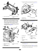
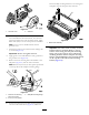
13.Apply242Loctite(blue)tothe2bolts(5/16x5/8
inch)andusethemtomountthebrushplatetothe
rollerbrushbearinghousing(Figure11).Torquethe
boltsto20to25N-m(15to19ft-lb).
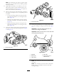
14.Checktomakesuretherollerbrushplateisparallelto
thecuttingunitsideplate.Ifitisnotparallel,proceed
asfollows:
•Loosenthe2angelocknutssecuringtheroller
brushmountingbrackettothecuttingunitside
plate(Figure11).
•Rotatetherollerbrushbearinghousinguntilthe
brushplateisparalleltothecuttingunitsideplate
(Figure11).
•Tightenthe2angelocknutssecuringtheroller
brushmountingbrackettothecuttingunitside
plate(Figure11).
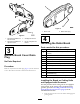
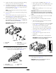
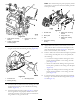
15.Loosenthe2boltssecuringeachrollerbrushbearing
housingtotherollerbrushmountingbracket(Figure
12andFigure13).
Figure12
1.Loosenthesebolts
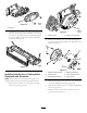
Figure13
1.Loosenthesebolts
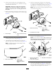
16.Positiontherollerbrushsoitisinlightcontactwith
(i.e.,justtouchingorrestingon)therearroller(Figure
14).
Important:Therollerbrushshaftmustnot
contactthecuttingunitsideplate.
Important:Heavybrushcontactontherollerwill
caseprematurebrushwear.
Figure14
1.Sideplate
4.Rearroller
2.Rollerbrush5.Ensurethatthereis
clearancehere.
3.Lightcontact
Note:Therollerbrushshaftmustbeparalleltothe
rearroller.
Note:Theorientationofthenon–driverollerbrush
bearinghousingshouldbethesameasdriveside
bearinghousing.
6