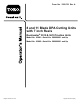
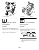
Form No. 3358-791 Rev A 8 and 11 Blade DPA Cutting Units with 7 inch Reels Reelmaster® 5510 & 5610 Traction Units Model No. 03681—Serial No. 280000001 and Up Model No. 03682—Serial No. 280000001 and Up Register at www.Toro.com.
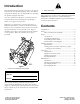
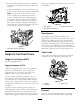
Introduction Figure 2 Read this information carefully to learn how to operate and maintain your product properly and to avoid injury and product damage. You are responsible for operating the product properly and safely. 1. Safety alert symbol This manual uses 2 other words to highlight information. Important calls attention to special mechanical information and Note emphasizes general information worthy of special attention. You may contact Toro directly at www.Toro.
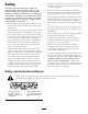
Safety Wearing safety glasses, safety shoes and a helmet is advisable and required by some local ordinances and insurance regulations. Hazard control and accident prevention are dependent upon the awareness, concern, and proper training of the personnel involved in the operation, transport, maintenance, and storage of the machine. Improper use or maintenance of the machine can result in injury or death. To reduce the potential for injury or death, comply with the following safety instructions.
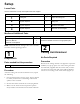
Setup Loose Parts Use the chart below to verify that all parts have been shipped. Procedure Description 1 2 3 4 Use Qty. Cutting unit 1 Inspect the cutting unit No parts required – Use the kickstand when tipping the cutting unit No parts required – Adjust the rear shield No parts required – Mount the counter weights Media and Additional Parts Description Parts catalog Operator’s Manual Certificate of Compliance Use Qty.
Figure 3 Figure 4 1. Cutting unit kickstand 1. Rear shield 3 2. Cap screw 4 Adjusting the Rear Shield Mount the Counter Weights No Parts Required No Parts Required Procedure Procedure Under most conditions, best dispersion is attained when the rear shield is closed (front discharge). When conditions are heavy or wet, rear shield may be opened. All cutting units are shipped with the counter weight mounted to the left end of the cutting unit.
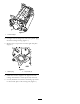
Figure 6 1. Counter weight 2. On right end of cutting unit, remove the plastic plug from the bearing housing (Figure 7). 3. Remove the 2 cap screws from the right side plate (Figure 7). Figure 7 1. Plastic plug 2. Cap screw (2) 4. Install the counter weight to the right end of the cutting unit with the 2 screws previously removed. 5. Loosely install the 2 reel motor mounting cap screws to the left side plate of the cutting unit (Figure 7).
Product Overview Specifications Tractors These cutting units will mount on the Reelmaster 5510 & 5610 Traction Units. Height of Cut Cutting height is adjusted on the front roller by two vertical screws and held by two locking cap screws Height Of Cut Range Standard bench height of cut range is .250 inch (3 mm) to 1.00 inch (25 mm). Bench height of cut range with the High Height of Cut Kit installed is 1.00 inch (25 mm) to 2.00 inches (51 mm).
Cutting Unit Accessories and Kits (see parts catalog for part numbers) however, effective height of cut is raised and quality of cut is reduced. Scrapers (Wiehle, Shoulder, Rear roller, Full Front Roller): Fixed scrapers for all optional rollers are available for reducing grass build up on rollers which can affect height of cut settings. Roller Rebuild Kit: Includes all the bearings, bearing nuts, inner seals and outer seals required to rebuild a roller.
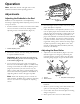
Operation Note: Determine the left and right sides of the machine from the normal operating position. Adjustments Adjusting the Bedknife to the Reel Bedknife to reel adjustment is accomplished by loosening or tightening bedbar adjusting screws, located on top of mower. Figure 9 4. Check for light contact at other end of reel using paper and adjust as required. 5.
6. Re-secure roller bracket and spacers to underside of side plate mounting flanges with nuts previously removed. allowing the spinning reel to pull more grass up into the bedknife. 7. Verify that bedknife to reel contact is correct. Tip mower to expose front and rear rollers and bedknife. Note: The position of the rear roller to the reel is controlled by the machining tolerances of the assembled components and paralleling is not required.
Height of Cut Chart HOC Setting Aggressiveness of Cut No. of Rear Spacers No. of Chain Links With Groomer kits installed 0.250" Less Normal More 0 0 1 5 5 5 Y Y - 0.375" Less Normal More 0 1 2 5 5 5 Y Y - 0.500" Less Normal More 0 1 2 5 5 5 Y Y Y 0.625" Less Normal More 1 2 3 5 5 5 Y Y - 0.750" Less Normal More 2 3 4 5 5 5 Y Y - 0.875" Less Normal More 2 3 4 5 5 5 Y Y - 1.000" Less Normal More 3 4 5 5 5 4+ Y Y - 1.125" Less Normal More 4 5 6 5 5 5 - 1.
Adjusting the Height of Cut Note: For heights of cut greater than 1.00" the High Height of Cut Kit must be installed. 1. Loosen locknuts securing height-of-cut arms to cutting unit side plates (Figure 14). Figure 16 Figure 14 Important: When set properly, the rear and front rollers will contact the gauge bar and the screw will be snug against the bedknife. This ensures that the height-of-cut is identical at both ends of the bedknife. 3. Adjusting screw 1. Height-of-cut arm 2. Locknut 2.
Cutting Unit Characteristics Note: Over time, the chamfer (Figure 18) will need to be reground as it is only designed to last 40% of the bedknife life. The dual knob bedknife-to-reel adjustment system incorporated in this cutting unit simplifies the adjustment procedure needed to deliver optimum mowing performance.
Note: The recommended top and front bedknife grind angle is 3 to 7 degrees (Figure 19). Figure 19 1.
Maintenance Lubrication Each cutting unit has (6) grease fittings (Figure 21) that must be lubricated regularly with No. 2 General Purpose Lithium Base Grease. Figure 22 The lubrication points are front roller (2), rear roller (2) and reel bearing (2). 1. Bedknife adjusting knob Note: Lubricating cutting units immediately after washing helps purge water out of bearings and increases bearing life. 2.
Note: Reel bearings do not require preload. Over tightening reel bearing adjuster nut will damage reel bearings. 4. Retighten set screw securing bearing adjusting nut to bearing housing. Torque to 12-15 in-lb. Servicing the Bedbar Removing the Bedbar 1. Turn bedbar adjuster screws, counterclockwise, to back bedknife away from reel (Figure 25). Figure 27 1. Bedbar bolt 2. Nut 3. Steel washer 4. Nylon washer Assembling the Bedbar 1.
Servicing the Roller outer seals to rebuild a roller. The Roller Rebuild Tool Kit includes all the tools and the installation instructions required to rebuild a roller with the roller rebuild kit. Refer to your parts catalog or contact your distributor for assistance. A Roller Rebuild Kit, Part No. 114–5430 and a Roller Rebuild Tool Kit, Part No. 115–0803 (Figure 29) are available for servicing the roller. The Roller Rebuild Kit includes all the bearings, bearing nuts, inner seals and Figure 29 1. 2. 3.
Notes: 18
Notes: 19
The Toro General Commercial Products Warranty A Two-Year Limited Warranty Conditions and Products Covered The Toro Company and its affiliate, Toro Warranty Company, pursuant to an agreement between them, jointly warrant your Toro Commercial Product (“Product”) to be free from defects in materials or workmanship for two years or 1500 operational hours*, whichever occurs first.