Form No. 3354–719 Rev B Verticutter Reelmaster 5510/5610 Series Cutting Unit with 7in Reel Model No. 03684—Serial No.
Contents Introduction . . . . . . . . . . . . . . . . . . . . . . . . . . . . . . . . Safety . . . . . . . . . . . . . . . . . . . . . . . . . . . . . . . . . . . . . Safe Operating Practices . . . . . . . . . . . . . . . . . . . . Safety and Instruction Decals . . . . . . . . . . . . . . . . Setup . . . . . . . . . . . . . . . . . . . . . . . . . . . . . . . . . . . . . Loose Parts . . . . . . . . . . . . . . . . . . . . . . . . . . . . . . Install Transport Rollers . . . . . . . . . . . . . . . . . . . .
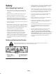
Safety • Remove all debris or other objects that might be picked up and thrown by the verticutter reel blades. Keep all bystanders away from the working area. Safe Operating Practices • If the verticutter blades strike a solid object or the unit vibrates abnormally, stop and shut the engine off. Check the verticutters for damaged parts. Repair any damage before restarting and operating the verticutters.
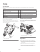
Setup Loose Parts Note: Use this chart as a checklist to ensure that all parts have been received. Without these parts, total setup cannot be completed. Qty. Description Use Transport roller assembly 2 Use when the verticutters are lowered to the shop floor Cotter pin 2 Use to secure transport rollers O–ring 1 For use with reel motor bearing housing Operator’s manual 1 Read before operating.
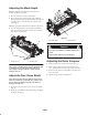
Adjusting the Blade Depth Note: The maximum recommended setting is 1/4 in. (6 mm) deep blade penetration. 1. Place the verticutter reel on a level surface. 2. Place 2 gauge bars, which have the desired depth of blade penetration below the ground, under the front and rear rollers of the verticutter reel (on each end of the reel) (Fig. 3). Note: The verticutter blades must not touch the gauge bars. 3. Turn the adjusting bolt on each height-of-cut bracket (Fig.
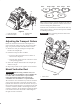
Motor Weight Weight #4 4 Motor Weight #1 Motor Weight Motor #5 Weight #2 Motor #3 Figure 6 Note: Counterweights are shipped installed to the right end of the verticutters. The capscrews on the left end are to be used for securing the hydraulic motor. 2 1 Verticutter reels are mounted to traction unit the same way cutting units are. Refer to Traction Unit Operator’s Manual for mounting instructions. 3 Figure 5 1. Front roller scraper 2.
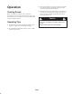
Operation 3. Power requirements to operate the verticutter reels will vary with turf and soil conditions. Travel speed may need to be reduced in some conditions. Training Period 4. When operating in turf conditions where much debris is encountered, or unusually heavy thatch, open the front and rear discharge shields to help allow the debris to discharge from the reel. Before operating the verticutter reels, evaluate the performance of the reel at the desired setting.
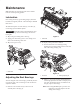
Maintenance Note: Determine the left and right sides of the machine from the normal operating position. Lubrication Each cutting unit has (7) grease fittings (Fig. 8) that must be lubricated regularly with No. 2 General Purpose Lithium Base Grease. The lubrication points are front roller (2), rear roller (2), reel bearing (2) and bedknife adjuster. 1 Important Lubricating cutting units immediately after washing helps purge water out of bearings and increases bearing life. Figure 9 1.
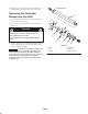
3. Retighten set screw securing bearing adjusting nut to bearing housing. Torque set screw to 12–15 in–lbs. This end in vise Removing the Verticutter Blades from the Shaft 1 1. Secure the end of the verticutter shaft, which has only one washer and nut, in a vise. 2. On other end of shaft, rotate nut counter–clockwise. Remove nut. Caution The blades are extremely sharp and may have burrs that will cut your hands. 6 Use caution when removing the blades from the shaft. 5 3.
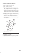
Install Verticutter Blades 1. First, assemble a reel blade (Fig. 11). 2. Next, assemble a large spacer. 3. Do not invert reel blades when reassembling on reel shaft. If the blades are inverted, the blades that are in use, (rounded) will be mixed with the sharp ends of the blades which were not in use. This will cause unsatisfactory performance in the verticutter reel unit. Attention should always be taken when disassembling verticutter blades from reel. 4.
The Toro General Commercial Products Warranty A Two-Year Limited Warranty Conditions and Products Covered The Toro Company and its affiliate, Toro Warranty Company, pursuant to an agreement between them, jointly warrant your Toro Commercial Product (“Product”) to be free from defects in materials or workmanship for two years or 1500 operational hours*, whichever occurs first.