Form No. 3391-958 Rev A Verticutter Reelmaster® 5210/5410 Series Cutting Unit with 5in Reel or Reelmaster® 5510/5610 Series Cutting Unit with 7in Reel Model No. 03664—Serial No. 315000001 and Up Model No. 03684—Serial No. 315000001 and Up Register at www.Toro.com.
Contents WARNING CALIFORNIA Proposition 65 Warning This product contains a chemical or chemicals known to the State of California to cause cancer, birth defects, or reproductive harm. Safety ........................................................................... 3 Safety and Instructional Decals ................................. 3 Setup ............................................................................ 4 1 Inspecting the Verticutter.......................................
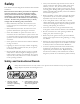
Safety • Always wear substantial, slip-resistant footwear. Do not operate verticutters while wearing sandals, tennis shoes, sneakers, or shorts. Also, do not wear loose fitting clothing which could get caught in moving parts. Always wear long pants. Wearing safety glasses, safety shoes and a helmet is advisable and required by some local ordinances and insurance regulations. This machine has been designed in accordance with EN ISO 5395:2013.
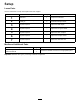
Setup Loose Parts Use the chart below to verify that all parts have been shipped. Procedure Description 1 2 3 4 5 6 7 Use Qty. Verticutter 1 Inspect the verticutter Transport roller assembly Cotter pin 2 2 Install the transport rollers. No parts required – Adjust the blade depth. No parts required – Adjust the rear grass shield. No parts required – Adjust the roller scrapers. No parts required – Adjust the transport rollers.
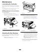
Note: Determine the left and right sides of the machine from the normal operating position. 2 Note: Whenever the verticutter has to be tipped to expose the verticutter blades, use the kick stand (supplied with traction unit) (Figure 2). Installing the Transport Rollers Parts needed for this procedure: 2 Transport roller assembly 2 Cotter pin Procedure Secure a transport roller bracket to each side plate pin with a cotter pin (Figure 3). Figure 2 1. Kick stand 1 Figure 3 1.
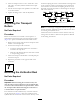
1 2 2 G012270 Figure 5 1 G012693 1. Rear grass shield 2. Pivot bolt Figure 4 1. Gauge bar 2. Adjusting bolt 2. Rotate the grass shield to the desired setting, and tighten the bolts (Figure 5). Note: The verticutter blades must not touch the gauge bars. CAUTION Do not open the rear shield so that it is higher than level to ground. 3. Turn the adjusting bolt on each height-of-cut bracket (Figure 4) so that the reel blades come in contact with the level surface on both ends.
locations requiring the motor to be mounted on the right end of the verticutter, install a counterweight on the left end of the verticutter. For the locations requiring the motor to be mounted on the left end, install a counterweight on the right end of the verticutter. 2. Move the scraper rods in or out to attain 0.0 to 0.03 inch (0.0 to 0.75 mm) clearance between the scraper and roller. 3. Ensure that the scraper rod is parallel to the roller and to the level surface. 4.
Product Overview Operation Specifications Note: Determine the left and right sides of the machine from the normal operating position. Model No. Net Weight 03664 124 lb. (56 kg) 03684 145 lb. (66 kg) Training Period Before operating the verticutter reels, evaluate the performance of the reel at the desired setting. Operate in a clear, unused area to determine if the desired results will be achieved. Adjust as desired. Operating Tips 1.
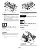
Maintenance Lubricating the Verticutter Each verticutter has 7 grease fittings (Figure 8) that must be lubricated weekly with No. 2 General Purpose Lithium Base Grease. The lubrication points are the front roller (2), the rear roller (2) the reel bearings (2) and the bedknife adjuster. 1 Important: Lubricating the cutting units immediately after washing helps purge water out of the bearings and increases bearing life. G012694 Figure 9 1. Wipe each grease fitting with a clean rag. 1. Reel shaft 2.
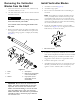
Removing the Verticutter Blades from the Shaft Install Verticutter Blades 1. Assemble a reel blade (Figure 12). 2. Assemble a large spacer. 1. Secure the end of the verticutter shaft, which has only one washer and nut, in a vise. 3. Do not invert the reel blades when reassembling on reel shaft. 2. On other end of shaft, rotate the nut counter-clockwise and remove the nut.
Optional Blade Spacing .50 inch Blade Spacing for Model 03664 To change the configuration of the verticutter from the standard .75 inch spacing to .50 inch spacing requires an additional (34) spacers, part no. 17-1580 and an additional (10) carbide blades, part no. 106-6355 or an additional (10) regular blades, part no. 17-1590 (Figure 13). 1 2 Figure 13 1. .50 inch spacing 2. .75 inch spacing 1.00 inch Blade Spacing for Model 03684 To change the configuration of the verticutter from the standard 1.
Servicing the Roller bearings, bearing nuts, inner seals and outer seals to rebuild a roller. The Roller Rebuild Tool Kit includes all the tools and the installation instructions required to rebuild a roller with the roller rebuild kit. Refer to your parts catalog or contact your distributor for assistance. A Roller Rebuild Kit, Part No. 114–5430 and a Roller Rebuild Tool Kit, Part No. 115–0803 (Figure 15) are available for servicing the roller. The Roller Rebuild Kit includes all the Figure 15 1.
Notes: 13
Declaration of Incorporation The Toro Company, 8111 Lyndale Ave. South, Bloomington, MN, USA declares that the following unit(s) conform(s) to the directives listed, when installed in accordance with the accompanying instructions onto certain Toro models as indicated on the relevant Declarations of Conformity. Model No. Serial No.
International Distributor List Distributor: Country: Phone Number: Distributor: Phone Number: 57 1 236 4079 Colombia Japan 81 3 3252 2285 Czech Republic 420 255 704 220 420 255 704 Slovakia 220 Argentina 54 11 4 821 9999 Russia 7 495 411 61 20 Ecuador 593 4 239 6970 Finland 358 987 00733 Agrolanc Kft Balama Prima Engineering Equip. B-Ray Corporation Hungary Hong Kong Korea 36 27 539 640 852 2155 2163 82 32 551 2076 Maquiver S.A. Maruyama Mfg. Co. Inc. Mountfield a.s.
Toro General Commercial Product Warranty A Two-Year Limited Warranty Conditions and Products Covered The Toro Company and its affiliate, Toro Warranty Company, pursuant to an agreement between them, jointly warrant your Toro Commercial product (“Product”) to be free from defects in materials or workmanship for two years or 1500 operational hours*, whichever occurs first. This warranty is applicable to all products with the exception of Aerators (refer to separate warranty statements for these products).