
Operator's Manual


Note:Determinetheleftandrightsidesofthemachine
fromthenormaloperatingposition.
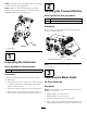
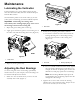
Note:Whenevertheverticutterhastobetipped
toexposetheverticutterblades,usethekickstand
(suppliedwithtractionunit)(
Figure2).
Figure2
1.Kickstand
1
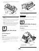
InspectingtheVerticutter
Partsneededforthisprocedure:
1Verticutter
Procedure
Aftertheverticutterisremovedfromthebox,inspect
thefollowing:
1.Checkeachendofthereelforgrease.Greaseshould
bevisiblyevidentinthereelbearingsandinternal
splinesofthereelshaft.
2.Ensurethatallnutsandboltsaresecurelytightened.
3.Makesurethecarrierframesuspensionoperates
freelyanddoesnotbindwhenmovedbackandforth.
2
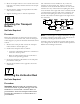
InstallingtheTransportRollers
Partsneededforthisprocedure:
2Transportrollerassembly
2
Cotterpin
Procedure
Secureatransportrollerbrackettoeachsideplatepin
withacotterpin(Figure3).
Figure3
1.Transportrollerassembly
2.Cotterpin
Note:Therollershouldbepositionedtotherearof
theverticutter.
3
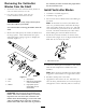
AdjustingtheBladeDepth
NoPartsRequired
Procedure
Note:Themaximumrecommendedbladepenetration
depthsareasfollows:
•Model03664is1/8inch(3mm).
•Model03684is1/4inch(6mm).
1.Placetheverticutterreelonalevelsurface.
2.Place2gaugebars,whichhavethedesireddepthof
bladepenetrationbelowtheground,underthefront
5