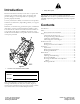
Form No. 3384-608 Rev B 8 and 11-Blade DPA Cutting Unit with 7in Reel Reelmaster® 5510/5610 Series Traction Unit Model No. 03693—Serial No. 314000001 and Up Model No. 03696—Serial No. 313000001 and Up Model No. 03697—Serial No. 313000001 and Up Register at www.Toro.com.
Figure 2 Introduction 1. Safety alert symbol Read this information carefully to learn how to operate and maintain your product properly and to avoid injury and product damage. You are responsible for operating the product properly and safely. This manual uses 2 words to highlight information. Important calls attention to special mechanical information and Note emphasizes general information worthy of special attention. You may contact Toro directly at www.Toro.
Safety and required by some local ordinances and insurance regulations. • Remove all debris or other objects that might be picked To control hazards and prevent accidents, it is essential that those who operate, transport, maintain, and store the machine be aware, concerned, and properly trained. Improperly using the machine can result in injury or death. To reduce the potential for injury or death, comply with the following safety instructions. up and thrown by the cutting unit reel blades.
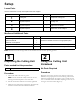
Setup Loose Parts Use the chart below to verify that all parts have been shipped. Procedure Description 1 2 3 4 Use Qty. Cutting unit 1 Inspect the cutting unit. No parts required – Use the kickstand when tipping the cutting unit. No parts required – Adjust the rear shield. No parts required – Mount the counter weights. Media and Additional Parts Description Use Qty. Parts catalog Operator's Manual Certificate of Compliance 1 1 1 Review the material and save in an appropriate place.
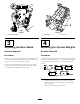
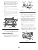
Figure 3 Figure 4 1. Cutting unit kickstand 1. Rear shield 3 2. Cap screw 4 Adjusting the Rear Shield Mounting the Counter Weights No Parts Required No Parts Required Procedure Procedure Under most conditions, best dispersion is attained when the rear shield is closed (front discharge). When conditions are heavy or wet, the rear shield may be opened. All cutting units are shipped with the counter weight mounted to the left end of the cutting unit.
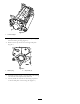
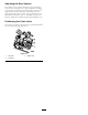
Figure 6 1. Counter weight 3. On right end of cutting unit, remove the plastic plug from the bearing housing (Figure 7). 4. Remove the 2 cap screws from the right side plate (Figure 7). 1 G003321 2 Figure 7 1. Plastic plug 2. Cap screw (2) 5. Install the counter weight to the right end of the cutting unit with the 2 screws previously removed. 6. Loosely install the 2 reel motor mounting cap screws to the left side plate of the cutting unit (Figure 7).
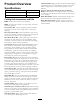
Product Overview Full Front Roller: Helps produce more pronounced striping (repeated cutting in the same direction/path); however, the effective height of cut is raised and the quality of cut is reduced. Scrapers (Wiehle, Shoulder, Rear roller, Full Front Roller): Fixed scrapers for all optional rollers are available for reducing grass buildup on rollers which can affect height of cut settings.
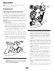
Operation Note: Determine the left and right sides of the machine from the normal operating position. Adjustments Adjusting the Bedknife to the Reel Use this procedure to set the bedknife to the reel and to check the condition of the reel and bedknife and their interaction. After completing this procedure, always test the cutting unit performance under your field conditions. You may need to make further adjustments to obtain optimal cutting performance.
sides prevents the shim from passing through on both sides. The bedknife is now parallel to the reel. Note: This procedure should not be needed on daily adjustments, but should be done after grinding or disassembly. 9. From this position (i.e. one click in and shim not passing through) turn the bedbar adjusters clockwise one click each. Figure 11 Note: Each click turned moves the bedknife 0.022 mm (0.0009 inch). Do not over tighten the adjusting screws. 1. Spacer 3. Side plate mounting flange 2.
Adjusting the Rear Spacers The number of rear spacers determines the aggressiveness of cut for the cutting unit. For a given height of cut, adding spacers, below the side plate mounting flange, increases the aggressiveness of the cutting unit. All cutting units on a given machine must be set to the same aggressiveness of cut (Number of rear spacers, part no. 106-3925), otherwise the after-cut appearance could be negatively affected (Figure 14).
Height of Cut Chart Terms Turf Compensation Settings Height of Cut Setting (HOC) The turf compensation spring transfers the weight from the front to the rear roller. (This helps to reduce a wave pattern in the turf, also known as marcelling or bobbing.) The desired height of cut. Important: Make spring adjustments with the cutting unit mounted to the traction unit, pointing straight ahead and lowered to the shop floor.
Height of Cut Chart These are the recommended height of cut settings when a groomer kit is installed on the cutting unit. HOC Setting Aggressiveness of Cut No. of Rear Spacers No. of Chain Links With Groomer kits installed 0.64 cm (0.250 inch) Less Normal More 0 0 1 5 5 5 Y Y - 0.95 cm (0.375 inch) Less Normal More 0 1 2 5 5 5 Y Y - 1.27 cm (0.500 inch) Less Normal More 0 1 2 5 5 5 Y Y Y 1.56 cm (0.625 inch) Less Normal More 1 2 3 5 5 5 Y Y - 1.91 cm (0.
Adjusting the Height of Cut Note: For heights of cut greater than 2.54 cm (1.00 inch) the High Height of Cut Kit must be installed. 1. Loosen the locknuts securing the height-of-cut arms to the cutting unit side plates (Figure 16). Figure 18 Figure 16 5. Tighten the nuts to secure the adjustment. Do not overtighten the nuts. Tighten enough to remove play from the washer. 3. Adjusting screw 1. Height-of-cut arm 2.
Bedknife/Height of Cut Chart Bedknife Part No. Bedknife Lip Height * Height of Cut Low HOC (Optional) 110–4084 5.6 mm (0.220 inch) 6.4–12.7 mm (0.250-0.500 inch) Premium Low HOC (Optional) 125-2771 5.6 mm (0.220 inch) 6.4–12.7 mm (0.250-0.500 inch) Extended Low HOC (Optional) 120-1640 5.6 mm (0.220 inch) 6.4–12.7 mm (0.250-0.500 inch) EdgeMax® Low HOC (Production for Model 03693) 127–7132 5.6 mm (0.220 inch) 6.4–12.7 mm (0.250-0.
Figure 20 1. Lead-in chamfer on right end of bedknife Note: Do not make lead-in chamfer too large as it may cause turf tufting.
Servicing the Bedknife The bedknife service limits are listed in the following charts Important: Operating the cutting unit with the bedknife below the service limit may result in poor after-cut appearance and reduce the structural integrity of the bedknife for impacts. Bedknife Service Limit Chart Bedknife Part No. Bedknife Lip Height * Service Limit* Low HOC (Optional) 110–4084 5.6 mm (0.220 inch) 4.8 mm (0.190 inch) 5/5 Degrees Premium Low HOC (Optional) 125-2771 5.6 mm (0.220 inch) 4.
Maintenance 2. Using a rag or thickly padded glove, hold on to the reel blade and try to move the reel assembly side to side (Figure 25). Lubrication Each cutting unit has 6 grease fittings (Figure 23) that must be lubricated regularly with No. 2 general-purpose, lithium-base grease. 1 g020697 Figure 25 3. If end play exists, proceeded as follows: g017023 A. Loosen external set screw securing bearing adjusting nut to bearing housing located on the left side of the cutting unit (Figure 26).
Servicing the Bedbar Removing the Bedbar 1. Turn bedbar adjuster screws counterclockwise to back the bedknife away from the reel (Figure 27). Figure 29 1. Bedbar bolt 2. Nut Figure 27 1. Bedbar adjusting screw 3. Bedbar 2. Spring tension nut 4. Washer 3. Steel washer 4. Nylon washer Assembling the Bedbar 2. Back out the spring tension nut, until the washer is no longer tensioned against the bedbar (Figure 27). 1.
Servicing the HD Dual Point Adjusters (DPA) 4. Install a wave washer onto the adjuster shaft and slide the adjuster shaft into the flange bushings in the cutting unit frame (Figure 31). 1. Remove all parts (refer to Installation Instructions for HD DPA Kit Model No. 120–7230 and to Figure 31). 5. Secure the adjuster shaft with a flat washer and lock nut (Figure 31). Torque the lock nut to 20 to 27 N-m (15 to 20 ft-lb). 2.
Servicing the Roller bearings, bearing nuts, inner seals and outer seals to rebuild a roller. The Roller Rebuild Tool Kit includes all the tools and the installation instructions required to rebuild a roller with the roller rebuild kit. Refer to your parts catalog or contact your authorized Toro dealer for assistance. The roller Rebuild Kit, Part No. 114–5430 and the Roller Rebuild Tool Kit, Part No. 115–0803 (Figure 32) are available for servicing the roller.
Notes: 21
Notes: 22
Declaration of Incorporation The Toro Company, 8111 Lyndale Ave. South, Bloomington, MN, USA declares that the following unit(s) conform(s) to the directives listed, when installed in accordance with the accompanying instructions onto certain Toro models as indicated on the relevant Declarations of Conformity. Model No. Serial No.
The Toro Total Coverage Guarantee A Limited Warranty Conditions and Products Covered The Toro Company and its affiliate, Toro Warranty Company, pursuant to an agreement between them, jointly warrant your Toro Commercial product (“Product”) to be free from defects in materials or workmanship for two years or 1500 operational hours*, whichever occurs first. This warranty is applicable to all products with the exception of Aerators (refer to separate warranty statements for these products).