
Operator's Manual

sidespreventstheshimfrompassingthroughonboth
sides.Thebedknifeisnowparalleltothereel.
Note:Thisprocedureshouldnotbeneededondaily
adjustments,butshouldbedoneaftergrindingor
disassembly.
9.Fromthisposition(i.e.oneclickinandshimnot
passingthrough)turnthebedbaradjustersclockwise
oneclickeach.
Note:Eachclickturnedmovesthebedknife0.022
mm(0.0009inch).Donotovertightentheadjusting
screws.
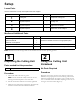
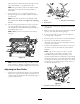
10.Testthecuttingperformancebyinsertingalongstrip
ofcuttingperformancepaper(Toropartnumber
125-5610)betweenreelandbedknife,perpendicularto
thebedknife(Figure10).
Note:Slowlyrotatethereelforward;itshouldcut
thepaper.
Figure10
Note:Shouldexcessivereeldragbeevident,itwillbe
eithernecessarytobacklaporregrindthecuttingunit
toachievethesharpedgesneededforprecisioncutting.
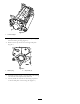
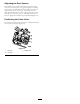
AdjustingtheRearRoller
1.Adjusttherearrollerbrackets(Figure11)tothedesired
heightofcutrangebypositioningtherequiredamount
ofspacersbelowthesideplatemountingange(Figure
11)pertheHOCChart.
Figure11
1.Spacer3.Sideplatemountingange
2.Rollerbracket
2.Raisetherearofcuttingunitandplaceablockunder
thebedknife.
3.Removethe2nutssecuringeachrollerbracketandthe
spacertoeachsideplatemountingange.
4.Lowertherollerandthescrewsfromthesideplate
mountingangesandspacers.
5.Placethespacersontothescrewsontherollerbrackets.
6.Re-securetherollerbracketandthespacersto
undersideofthesideplatemountingangeswiththe
nutspreviouslyremoved.
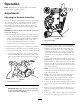
7.Verifythatthebedknifetoreelcontactiscorrect.Tip
themowertoexposefrontandrearrollersandthe
bedknife.
Note:Thepositionoftherearrollertothereel
iscontrolledbythemachiningtolerancesofthe
assembledcomponents,andsoparallelingisnot
required.Alimitedamountofadjustmentispossibleby
settingthecuttingunitonasurfaceplateandloosening
thesideplatemountingcapscrews(Figure12).Adjust
andtightenthecapscrews.Torquethecapscrewsto
27–36N-m(240-320ft.-lb).
g020552
Figure12
1.Sideplatemountingcapscrews
9