Form No. 3391-995 Rev A 8 or 11 Blade DPA Cutting Unit with 5in Reel Reelmaster® 5210/5410 Series Traction Unit Model No. 03694—Serial No. 315000001 and Up Model No. 03695—Serial No. 315000001 and Up Register at www.Toro.com.
WARNING Model No. CALIFORNIA Proposition 65 Warning This product contains a chemical or chemicals known to the State of California to cause cancer, birth defects, or reproductive harm. Serial No. This manual identifies potential hazards and has safety messages identified by the safety alert symbol (Figure 2), which signals a hazard that may cause serious injury or death if you do not follow the recommended precautions. This product complies with all relevant European directives.
Safety sneakers or shorts. Also, do not wear loose fitting clothing which could get caught in moving parts. Always wear long pants and substantial shoes. Wearing safety glasses, safety shoes and a helmet is advisable and required by some local ordinances and insurance regulations. This machine has been designed in accordance with EN ISO 5395:2013.
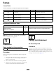
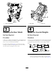
Setup Loose Parts Use the chart below to verify that all parts have been shipped. Procedure Description 1 2 3 4 Use Qty. Cutting unit 1 Inspect the cutting unit No parts required – Use the kickstand when tipping the cutting unit No parts required – Adjust the rear shield No parts required – Mount the counter weights Media and Additional Parts Description Use Qty.
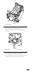
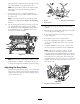
Figure 3 Figure 4 1. Cutting unit kickstand 1. Rear shield 3 2. Cap screw 4 Adjusting the Rear Shield Mount the Counter Weights No Parts Required No Parts Required Procedure Procedure Under most conditions, best dispersion is attained when the rear shield is closed (front discharge). When conditions are heavy or wet, rear shield may be opened. All cutting units are shipped with the counter weight mounted to the left end of the cutting unit.
Figure 6 1. Counter weight 2. On right end of cutting unit, remove the plastic plug from the bearing housing (Figure 7). 3. Remove the 2 cap screws from the right side plate (Figure 7). 1 G003321 2 Figure 7 1. Plastic plug 2. Cap screw (2) 4. Install the counter weight to the right end of the cutting unit with the 2 screws previously removed. 5. Loosely install the 2 reel motor mounting cap screws to the left side plate of the cutting unit (Figure 7).
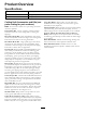
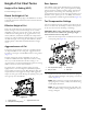
Product Overview Specifications Model Number Net Weight 03694 51 kg (112 lb) 03695 52 kg (116 lb) Cutting Unit Accessories and Kits (see parts catalog for part numbers) Long Rear Roller: Helps reduce over-lap marks and mismatch between cutting units for warm season grasses (Bermuda, Zoysia, Paspalum). Full Front Roller: Helps produce more pronounced striping (repeated cutting in the same direction/path), however, effective height of cut is raised and quality of cut is reduced.
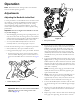
Operation Note: Determine the left and right sides of the machine from the normal operating position. Adjustments Adjusting the Bedknife to the Reel Use this procedure to set the bedknife to the reel and to check the condition of the reel and bedknife and their interaction. After completing this procedure, always test the cutting unit performance under your field conditions. You may need to make further adjustments to obtain optimal cutting performance.
sides prevents the shim from passing through on both sides. The bedknife is now parallel to the reel. Note: This procedure should not be needed on daily adjustments, but should be done after grinding or disassembly. 9. From this position (i.e. one click in and shim not passing through) turn the bedbar adjusters clockwise two clicks each. Figure 11 Note: Each click turned moves the bedknife 0.018 (0.0007 inches). Do not over tighten the adjusting screws. 1. Spacer 3. Side plate mounting flange 2.
Rear Spacers Height of Cut Chart Terms The number of rear spacers determines the aggressiveness of cut for the cutting unit. For a given height of cut, adding spacers, below the side plate mounting flange, increases the aggressiveness of the cutting unit. All cutting units on a given machine must be set to the same aggressiveness of cut (Number of rear spacers, part no. 119–0626), otherwise the after-cut appearance could be negatively affected (Figure 13).
Chain Links The location at which the lift arm chain is attached determines the rear roller pitch angle (Figure 15). Figure 15 1. Lift chain 2. U-Bracket 3. Bottom hole Groomer These are the recommended height of cut settings when a groomer kit is installed on the cutting unit.
Height of Cut Chart HOC Setting Aggressiveness of Cut No. of Rear Spacers No. of Chain Links With Groomer kits installed 0.64 cm (0.250 inches) Less Normal More 0 0 1 3+ 3+ 3 Y Y - 0.95 cm (0.375 inches ) Less Normal More 0 1 2 4 3 3 Y Y - 1.27 cm (0.500 inches) Less Normal More 0 1 2 4 3+ 3 Y Y Y 1.56 cm (0.625 inches) Less Normal More 1 2 3 4 3 3 Y Y - 1.91 cm (0.750 inches) Less Normal More 2 3 4 3+ 3 3 Y Y - 2.22 cm (0.875 inches) Less Normal More 2 3 4 4 3 3 Y Y - 2.
Adjusting the Height of Cut Note: For heights of cut greater than 2.54 cm (1.000 inch) the High Height of Cut Kit must be installed. 1. Loosen locknuts securing height-of-cut brackets to cutting unit side plates (Figure 16). Figure 18 Figure 16 Important: When set properly, the rear and front rollers will contact the gauge bar and the screw will be snug against the bedknife. This ensures that the height-of-cut is identical at both ends of the bedknife. 3. Adjusting screw 1. Height-of-cut bracket 2.
Extended Low HOC (Optional) 120–1640 5.6 mm (.220 inch) 6.4-12.7 mm (.250-.500 inch) Extended EdgeMax® Low HOC (Optional) 119–4280 5.6 mm (.220 inch) 6.4-12.7 mm (.250-.500 inch) EdgeMax® (Production) 108-9095 6.9 mm (.270 inch) 9.5-38.1 mm (.375-1.50 inch)* Standard (Optional) 108-9096 6.9 mm (.270 inch) 9.5-38.1 mm (.375-1.50 inch)* Heavy Duty (Optional) 110-4074 9.3 mm (.370 inch) 12.7-38.1 mm (.500-1.50 inch) Figure 20 * Warm season grasses may require the Low HOC bedknife for 12.
Servicing Bedknife The bedknife service limits are listed in the following charts. Important: Operating the cutting unit with the bedknife below the “service limit” may result in poor after-cut appearance and reduce the structural integrity of the bedknife for impacts. Bedknife Service Limit Chart Bedknife Part No. Bedknife Lip Height * Service Limit * Low HOC (Optional) 110-4084 5.6 mm (.220 inch) 4.8 mm (.190 inch) 5/5 Degrees Premium Low (Optional) 125–2771 5.6 mm (.220 inch) 6.4-12.7 mm (.
Maintenance Lubrication Each cutting unit has (6) grease fittings (Figure 24) that must be lubricated regularly with No. 2 General Purpose Lithium Base Grease. Figure 25 The lubrication points are front roller (2), rear roller (2) and reel bearing (2). 1. Bedknife adjusting knob Note: Lubricating cutting units immediately after washing helps purge water out of bearings and increases bearing life. 2.
Note: Reel bearings do not require preload. Over tightening reel bearing adjuster nut will damage reel bearings. 4. Retighten set screw securing bearing adjusting nut to bearing housing. Torque to 1.4-1.7 N-m (12-15 in-lb). Servicing the Bedbar Removing the Bedbar 1. Turn bedbar adjuster screws counterclockwise to back the bedknife away from reel (Figure 28). Figure 30 1. Bedbar bolt 2. Nut 3. Steel washer 4. Nylon washer Assembling the Bedbar 1.
Servicing the HD Dual Point Adjusters (DPA) 7. Loosely install the hardened washer, spring and spring tension nut onto adjuster screw. 8. Install the bedbar, positioning the mounting ears between washer and bedbar adjuster. 1. Remove all parts (refer to Installation Instructions for HD DPA Kit Model No. 120–7230 and to Figure 32). 2. Apply Never Seize to the inside of the bushing area on cutting unit center frame (Figure 32). 3.
Servicing the Roller inner seals and outer seals to rebuild a roller. The Roller Rebuild Tool Kit includes all the tools and the installation instructions required to rebuild a roller with the roller rebuild kit. Refer to your parts catalog or contact your distributor for assistance. A Roller Rebuild Kit, Part No. 114–5430 and a Roller Rebuild Tool Kit, Part No. 115–0803 (Figure 33) are available for servicing the roller. The Roller Rebuild Kit includes all the bearings, bearing nuts, Figure 33 1.
Notes: 20
Notes: 21
Declaration of Incorporation The Toro Company, 8111 Lyndale Ave. South, Bloomington, MN, USA declares that the following unit(s) conform(s) to the directives listed, when installed in accordance with the accompanying instructions onto certain Toro models as indicated on the relevant Declarations of Conformity. Model No. Serial No.
International Distributor List Distributor: Country: Phone Number: Distributor: Phone Number: 57 1 236 4079 Colombia Japan 81 3 3252 2285 Czech Republic 420 255 704 220 420 255 704 Slovakia 220 Argentina 54 11 4 821 9999 Russia 7 495 411 61 20 Ecuador 593 4 239 6970 Finland 358 987 00733 Agrolanc Kft Balama Prima Engineering Equip. B-Ray Corporation Hungary Hong Kong Korea 36 27 539 640 852 2155 2163 82 32 551 2076 Maquiver S.A. Maruyama Mfg. Co. Inc. Mountfield a.s.
Toro General Commercial Product Warranty A Two-Year Limited Warranty Conditions and Products Covered The Toro Company and its affiliate, Toro Warranty Company, pursuant to an agreement between them, jointly warrant your Toro Commercial product (“Product”) to be free from defects in materials or workmanship for two years or 1500 operational hours*, whichever occurs first. This warranty is applicable to all products with the exception of Aerators (refer to separate warranty statements for these products).