Form No. 3391-981 Rev B 8- or 11-Blade DPA Cutting Unit with 7in Reel Reelmaster® 5510/5610 Series Traction Unit Model No. 03693—Serial No. 315000001 and Up Model No. 03696—Serial No. 315000001 and Up Model No. 03697—Serial No. 315000001 and Up Register at www.Toro.com.
WARNING CALIFORNIA Proposition 65 Warning This product contains a chemical or chemicals known to the State of California to cause cancer, birth defects, or reproductive harm. This product complies with all relevant European directives. For details, please see the Declaration of Incorporation (DOI) at the back of this publication. Introduction g003317 Figure 1 1.
Contents Safety Safety ....................................................................... 3 Safety and Instructional Decals .......................... 4 Setup ........................................................................ 5 1 Inspecting the Cutting Unit ............................... 5 2 Using the Cutting Unit Kickstand ...................... 5 3 Adjusting the Rear Shield................................. 6 4 Mounting the Counter Weights......................... 6 Product Overview .........
Safety and Instructional Decals Safety decals and instructions are easily visible to the operator and are located near any area of potential danger. Replace any decal that is damaged or missing. The roller Rebuild Kit, Part No. 114–5430 decal93-6688 93-6688 1. Warning—read the Operator’s Manual before performing maintenance (no Operator’s Manual with this prototype unit; read the Quick Start Guide). 2. Cutting hazard of hand or foot—shut off the engine and wait for all moving parts to stop.
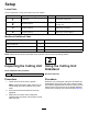
Setup Loose Parts Use the chart below to verify that all parts have been shipped. Procedure Description 1 2 3 4 Use Qty. Cutting unit 1 Inspect the cutting unit. No parts required – Use the kickstand when tipping the cutting unit. No parts required – Adjust the rear shield. No parts required – Mount the counter weights. Media and Additional Parts Description Use Qty. Parts Catalog Operator's Manual 1 1 Review the material and save it in an appropriate place.
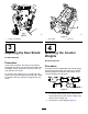
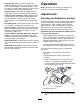
g003318 g003316 Figure 3 Figure 4 1. Cutting unit kickstand 1. Rear shield 3 2. Cap screw 4 Adjusting the Rear Shield Mounting the Counter Weights No Parts Required No Parts Required Procedure Procedure Under most conditions, the cutting unit produces best dispersion when you close the rear shield (front discharge). When conditions are heavy or wet, you may open the rear shield. All cutting units are shipped with the counter weight mounted to the left end of the cutting unit.
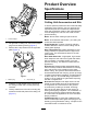
Product Overview Specifications Cutting Unit Weight 8 Blade 67 kg (147 lb) 11 Blade 69 kg (151 lb) Cutting Unit Accessories and Kits To ensure optimum performance and continued safety certification of the machine, use only genuine Toro replacement parts and accessories. Replacement parts and accessories made by other manufacturers could be dangerous, and such use could void the product warranty. g003320 Figure 6 Note: See the Parts Catalog for part numbers. 1. Counter weight 3.
Operation High HOC Kit: New front roller brackets and additional spacers for the rear roller allow the cutting unit to achieve heights of cut above 25 mm (1 inch). The new front roller brackets also move the front roller out farther to improve after-cut appearance.
Important: Make sure that the nuts on the back end of the bedbar adjusting screws are not resting on the work surface (Figure 9). 6. Turn the left bedbar adjuster clockwise until you can slide the shim can through the reel to bedknife gap with light drag. 7. Return to the right side and adjust as necessary to get light drag on the shim between the same blade and bedknife. 8.
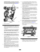
Adjusting the Rear Roller 1. Adjust the rear roller brackets (Figure 11) to the desired height-of-cut range by positioning the required amount of spacers below the side plate mounting flange (Figure 11) per the height-of-cut chart; refer to Height-of-Cut Chart (page 12). g020552 Figure 12 1. Side plate mounting cap screws g003324 Adjusting the Rear Spacers Figure 11 1. Spacer 3. Side plate mounting flange The number of rear spacers determines the aggressiveness of cut for the cutting unit.
Turf Compensation Settings Note: When operating the machine on rough The turf compensation spring transfers the weight from the front to the rear roller. (This helps to reduce a wave pattern in the turf, also known as marcelling or bobbing.) Note: Adjust the turf compensation setting if terrain, decrease the spring length by 12.7 mm (1/2 inch). the HOC setting or the aggressiveness of cut setting is changed.
Aggressiveness of Cut Cutting unit aggressiveness of cut has a significant impact on the performance of the cutting unit. Aggressiveness of Cut refers to the angle of the bedknife relative to the ground (Figure 17). The best cutting unit setup depends on your turf conditions and desired results. Experience with the cutting unit on your turf determines the best setting to use. You can adjust the aggressiveness of cut throughout the cutting season to allow for various turf conditions. g006502 Figure 17 1.
Height-of-Cut Adjustment Chart (cont'd.) HOC Setting 2.86 cm (1-1/4 inches) 3.18 cm (1-1/4 inches)* + 3.49 cm (1-3/8 inches)*+ 3.81 cm (1-1/2 inches)*+ 4.13 cm (1-5/8 inches)*+ 4.44 cm (1-3/4 inches)*+ 4.76 cm (1-7/8 inches)*+ 5.08 cm (2 inches)*+ Aggressiveness of Cut No. of Rear Spacers No.
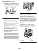
Adjusting the Height of Cut 3. Note: For heights of cut greater than 2.54 cm (1 inch), install the High Height-of-Cut Kit. 1. Loosen the locknuts securing the height-of-cut arms to the cutting unit side plates (Figure 18). Hook the screw head on the cutting edge of the bedknife and rest the rear end of the bar on the rear roller (Figure 20). 4. Rotate the adjusting screw until the front roller contacts the gauge bar (Figure 20).
Bedknife/Height-of-Cut Chart (cont'd.) Bedknife Part No. EdgeMax® Low HOC (Production for Model 03693) 127-7132 Extended Low HOC EdgeMax® (Optional) 119-4280 EdgeMax® (Production for Models 03696 and 03697) 108-9095 Standard (Optional) 108-9096 Heavy Duty (Optional) 110-4074 Bedknife Lip Height* Height of Cut 5.6 mm 6.4–12.7 mm (0.220 inch) (0.250 to 0.500 inch) 5.6 mm(0.220 inch) 6.4–12.7 mm (0.270 inch) (0.250 to 0.500 inch) 6.9 mm 9.5–38.1 mm (0.270 inch) (0.375 to 1.
Note: Do not make the lead-in chamfer too large as it may cause turf tufting. g006504 Figure 22 1. Lead-in chamfer on right end of bedknife Servicing the Bedknife Bedknife Chart The bedknife service limits and grind angles are listed in the following chart. Important: Operating the cutting unit with the bedknife below the service limit may result in poor after-cut appearance and reduce the structural integrity of the bedknife for impacts. Bedknife Dimension and Grind Angle Chart Bedknife Part No.
Recommended Top and Front Bedknife Grind Angles Refer to Figure 23 and the dimensions and angles listed in the Bedknife Chart (page 16). g025579 Figure 23 3. Front grind angle 1. Bedknife Service Limit* 2. Top grind angle Measuring the Bedknife Service Limit Note: All bedknife service limit measurements reference the bottom of the bedknife, refer to the Figure 24 and dimensions listed in the Bedknife Chart (page 16).
Maintenance Lubricating the Cutting Unit Each cutting unit has 6 grease fittings (Figure 25) that must be lubricated regularly with No. 2 lithium grease. g020697 Figure 27 3. If end play exists, proceeded as follows: A. Loosen external set screw securing bearing adjusting nut to bearing housing located on the left side of the cutting unit (Figure 28). g017023 Figure 25 1.
Servicing the Bedbar Removing the Bedbar 1. Turn bedbar adjuster screws counterclockwise to back the bedknife away from the reel (Figure 29). g003335 Figure 31 1. Bedbar bolt 2. Nut g006498 3. Steel washer 4. Nylon washer Figure 29 1. Bedbar adjusting screw 3. Bedbar 2. Spring tension nut 4. Washer 2. 3. Assembling the Bedbar Back out the spring tension nut, until the washer is no longer tensioned against the bedbar (Figure 29). 1.
Servicing the HD Dual Point Adjusters (DPA) 1. 2. 3. Remove all parts (refer to Installation Instructions for HD DPA Kit Model 120-7230 and to Figure 33). Apply anti-sieze compound to the inside of the bushing area on cutting unit center frame (Figure 33). Align the keys on flange bushings to the slots in the frame and install the bushings (Figure 33). 4. Install a wave washer onto the adjuster shaft and slide the adjuster shaft into the flange bushings in the cutting unit frame (Figure 33). 5.
14. Repeat this procedure on the other end of the cutting unit. 15. Adjust the bedknife to the reel. Servicing the Roller The roller Rebuild Kit, Part No. 114-5430 and the Roller Rebuild Tool Kit, Part No. 115-0803 (Figure 34) are available for servicing the roller. The Roller Rebuild Kit includes all the bearings, bearing nuts, inner seals and outer seals to rebuild a roller.
Declaration of Incorporation The Toro Company, 8111 Lyndale Ave. South, Bloomington, MN, USA declares that the following unit(s) conform(s) to the directives listed, when installed in accordance with the accompanying instructions onto certain Toro models as indicated on the relevant Declarations of Conformity. Model No. 03693 Serial No.
European Privacy Notice The Information Toro Collects Toro Warranty Company (Toro) respects your privacy. In order to process your warranty claim and contact you in the event of a product recall, we ask you to share certain personal information with us, either directly or through your local Toro company or dealer. The Toro warranty system is hosted on servers located within the United States where privacy law may not provide the same protection as applies in your country.
The Toro Warranty A Two-Year Limited Warranty Conditions and Products Covered The Toro Company and its affiliate, Toro Warranty Company, pursuant to an agreement between them, jointly warrant your Toro Commercial product (“Product”) to be free from defects in materials or workmanship for two years or 1500 operational hours*, whichever occurs first. This warranty is applicable to all products with the exception of Aerators (refer to separate warranty statements for these products).