
Operator's Manual
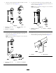

Note:Removethecounterweight(Figure11).
Figure11
1.Counterweight
2.Onrightendofcuttingunit,removetheplasticplug
fromthebearinghousing(Figure12).
3.Removethe2capscrewsfromtherightsideplate
(Figure12).
G003321
1
2
Figure12
1.Plasticplug
2.Capscrew(2)
4.Installthecounterweighttotherightendofthecutting
unitwiththe2screwspreviouslyremoved.
5.Looselyinstallthe2reelmotormountingcapscrews
totheleftsideplateofthecuttingunit(Figure12).
7
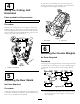
InstallingtheCuttingUnits
Partsneededforthisprocedure:
5/7LargeO-ring
2
Screw
Procedure
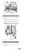
1.Insertathrustwasherontohorizontalshaftofpivot
knuckleasshowninFigure13.
Figure13
1.Carrierframe
4.Lynchpin
2.Pivotknuckle
5.Steeringlockingpin
3.Liftarmsteeringplate
2.Insertthehorizontalshaftofthepivotknuckleintothe
mountingtubeofthecarrierframe(Figure13).
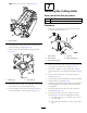
3.Securepivotknuckletocarrierframewithathrust
washer,atwasher,andaangeheadcapscrew(Figure
13).
4.Insertathrustwasherontoverticalshaftofpivot
knuckle(Figure13).
5.Ifremoved,inserttheverticalshaftofthepivotknuckle
intoliftarmpivothub(Figure13).
6.Guidethepivotknuckleinplacebetweenthe2rubber
centeringbumpersintheundersideoftheliftarm
steeringplate.
7.Insertthelynchpinintothecrossholeonthepivot
knuckleshaft(Figure13).
8.Securetheliftarmchaintothecuttingunitchain
bracket(Figure14)withthesnapperpinasfollows:
A.Oncuttingunits#1,4,5,6and7,onlyuse6of
thechainlinks.
B.Oncuttingunits#2and3,useall7ofthechain
links.
8