Form No. 3428-684 Rev A 8-Blade or 11-Blade DPA Cutting Unit Reelmaster® 6000-D Series Traction Unit Model No. 03698—Serial No. 403420001 and Up Model No. 03699—Serial No. 403420001 and Up Register at www.Toro.com.
This product complies with all relevant European directives. For details, please see the Declaration of Incorporation (DOI) at the back of this publication. Introduction This cutting unit is designed for cutting grass on well-maintained lawns in golf courses, parks, sports fields, and on commercial grounds. Using this product for purposes other than its intended use could prove dangerous to you and bystanders.
Contents Safety Safety ....................................................................... 3 General Safety ................................................... 3 Cutting Unit Safety.............................................. 3 Blade Safety ....................................................... 4 Safety and Instructional Decals .......................... 4 Setup ........................................................................ 5 1 Removing the Tipper Assemblies.....................
• Inspect the blade periodically for wear or damage. • Keep all parts in good working condition and all hardware tightened. Replace all worn or damaged decals. • Use care when checking the blades. Wrap the blades or wear gloves, and use caution when servicing the blades. Only replace or sharpen the blades; never straighten or weld them. • Use only accessories, attachments, and replacement parts approved by Toro. • On multi-bladed machines, take care as rotating 1 blade can cause other blades to rotate.
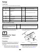
Setup Loose Parts Use the chart below to verify that all parts have been shipped. Procedure Description 1 No parts required 2 Lift chain Chain bracket U-bolt Nut Screw Washer Nut 3 4 5 Use Qty. – 5/7 5/7 5/7 10/14 5/7 5/7 5/7 Remove the tipper assemblies. Mount the lift brackets and chains. No parts required – Adjust the cutting unit No parts required – Mount the counterweights. Large O-ring Screw 5/7 2 Install the cutting units. Media and Additional Parts Description Qty.
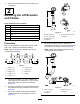
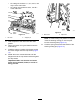
2. Disconnect the lift chains from the cutting units, if attached. 2 Mounting the Lift Brackets and Chains Parts needed for this procedure: 5/7 Lift chain 5/7 Chain bracket 5/7 U-bolt 10/14 g020546 Nut 5/7 Screw 5/7 Washer 5/7 Nut Figure 5 1. Lift arm number 5 = 38.1 cm (15 inches) 3. Lift arm numbers 1 and 5 = 10 degrees 2. Lift arm number 4 = 10 degrees Procedure 4. Mount a chain bracket to each lift arm with a U-bolt and 2 nuts.
5. On lift arm number 6 and number 7, position the brackets and U-bolts 36.8 cm (14.5 inches) behind the center line of the pivot knuckle (Figure 7). 3 Adjusting the Cutting Unit Note: Rotate the brackets 10 degrees to the outboard side of the machine. No Parts Required Procedure 1. Adjust the bedknife to the reel. 2. Adjust the rear roller for your height-of-cut requirements. 3. Set the height of cut. 4. Adjust the rear shield if necessary.
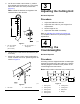
1. On cutting unit numbers 2, 4, and 6, remove the 2 cap screws securing the counterweight to the left end of the cutting unit. 5 Note: Remove the counterweight (Figure 10). Installing the Cutting Units Parts needed for this procedure: 5/7 2 Large O-ring Screw Procedure 1. Insert a thrust washer onto the horizontal shaft of the pivot knuckle as shown in Figure 12. g003320 Figure 10 1. Counterweight 2. 3.
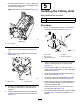
• On cutting unit numbers 1, 4, 5, 6, and 7, use only 6 of the chain links. • On cutting unit numbers 2 and 3, use all 7 of the chain links. g004127 Figure 14 g006542 1. Reel motor Figure 13 1. Lift chain 9. 2. Cap screw 2. Snapper pin Note: If a fixed cutting unit position is required, insert the steering locking pin into the pivot knuckle mounting hole (Figure 12). Coat the spline of the reel motor with clean grease. 10. Oil the reel motor O-ring and install it onto the motor flange. 11.
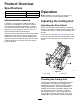
Product Overview Specifications Cutting Unit Operation Weight 8 blade 67 kg (147 lb) 11 blade 69 kg (151 lb) Note: Determine the left and right sides of the machine from the normal operating position. Attachments/Accessories Adjusting the Cutting Unit A selection of Toro approved attachments and accessories is available for use with the machine to enhance and expand its capabilities. Contact your Authorized Service Dealer or authorized Toro distributor or go to www.Toro.
Prior to mowing each day, or as required, check each cutting unit to verify proper bedknife-to-reel contact. This must be performed regardless of whether the quality of cut is acceptable. 1. Lower the cutting units onto a hard surface, shut off the engine, and remove the ignition key. 2. Slowly rotate the reel in a reverse direction, listening for reel-to-bedknife contact. If no contact is evident, turn the bedknife adjusting knobs clockwise, 1 click at a time, until you feel and hear light contact.
Note: This procedure should not be needed on daily adjustments, but should be done after grinding or disassembly. 9. From this position (i.e., 1 click in and shim not passing through) turn the bedbar adjusters clockwise 1 click each. Note: Each click turned moves the bedknife 0.022 (0.0009 inches). Do not overtighten the adjusting screws. 10. g019940 Figure 17 1.
2. Raise the rear of the cutting unit and place a block under the bedknife. 3. Remove the 2 nuts securing each roller bracket and spacer to each side-plate mounting flange. 4. Lower the roller and screws from the side-plate mounting flanges and spacers. 5. Place the spacers onto the screws on the roller brackets. 6. Secure the roller bracket and spacers to the underside of the side-plate mounting flanges with the nuts previously removed. 7. Verify that the bedknife-to-reel contact is correct.
2. Loosen the nut on the gauge bar (Figure 23) and set the adjusting screw to the desired height of cut. 6. Note: Do not overtighten the nuts. Tighten them just enough to remove play from the washer. g003327 Figure 23 1. Gauge bar 2. Height-adjusting screw 4. Holes used for setting Groomer HOC 5. Hole not used 3. Nut 3. Measure the distance between the bottom of the screw head and the face of the bar to get the height of cut. 4.
Height-of-Cut Chart HOC Setting 0.64 cm (0.250 inches) 0.95 cm (0.375 inches ) 1.27 cm (0.500 inches) 1.56 cm (0.625 inches) 1.91 cm (0.750 inches) 2.22 cm (0.875 inches) 2.54 cm (1.000 inches) 2.86 cm (1.125 inches) 3.18 cm (1.250 inches)*+ 3.49 cm (1.375 inches)*+ 3.81 cm (1.500 inches)*+ 4.13 cm (1.625 inches)*+ 4.44 cm (1.750 inches)*+ 4.76 cm (1.875 inches)*+ 5.08 cm (2.000 inches)*+ * The High HOC Kit (Part No. Aggressiveness of Cut No.
Use the following chart to determine which bedknife is best suited for the desired height of cut. Bedknife/Height of Cut Chart Part No. Bedknife Bedknife Lip Height Height of Cut 110-4084 5.6 mm 6.4 to 12.7 mm (0.220 inch) (0.250 to 0.500 inch) 5.6 mm 6.4 to 12.7 mm 137-0832 EdgeMax® Low HOC (Optional) (0.220 inch) (0.250 to 0.500 inch) 120-1640 5.6 mm 6.4 to 12.7 mm Extended Low HOC (Optional) (0.220 inch) (0.250 to 0.500 inch) 5.6 mm 6.4 to 12.7 mm 119-4280 Extended EdgeMax® Low HOC (Optional) (0.
g006502 Figure 26 1. Rear spacers 3. Aggressiveness of cut 2. Side-plate mounting flange Rear Spacers The number of rear spacers determines the aggressiveness of cut for the cutting unit. For a given height of cut, adding spacers, below the side-plate mounting flange, increases the aggressiveness of the cutting unit. All cutting units on a given machine must be set to the same aggressiveness of cut (number of rear spacers, Part No.
Maintenance Using the Kickstand When Tipping the Cutting Unit Whenever you have to tip the cutting unit to expose the bedknife and the reel, prop up the rear of the cutting unit with the kickstand (supplied with the traction unit) to make sure that the nuts on the back end of the bedbar adjusting screws are not resting on the work surface (Figure 27). g034188 Figure 28 1. Relief valve Adjusting the Reel Bearings To ensure long life of the reel bearings, periodically check if reel end play exists.
g020697 Figure 30 3. If end play exists, proceeded as follows: A. Loosen the external setscrew securing the bearing adjuster nut to bearing housing located on the left side of the cutting unit (Figure 31). g003332 Figure 31 1. Setscrew B. 2. Adjuster nut Using a 1-3/8 inch socket wrench, slowly tighten the reel-bearing adjustment nut until no end play of the reel exists. If adjusting the nut does not eliminate reel end play, replace the reel bearings.
Servicing the Bedknife The bedknife service limits are listed in the following chart. Important: Operating the cutting unit with the bedknife below the service limit may result in poor after-cut appearance and reduce the structural integrity of the bedknife for impacts. Bedknife Service Limit Chart Bedknife Part Bedknife Lip Height* Service Limit* EdgeMax® Low HOC (Optional) 137-0832 5.6 mm (0.220 inch) 6.4 to 12.7 mm (0.250 to 0.500 inch) 10/5 degrees Low HOC (Optional) 110-4084 5.6 mm (0.
Checking the Top Grind Angle Servicing the Bedbar The angle that you use to grind your bedknives is very important. Removing the Bedbar Use the angle indicator (Toro Part No. 131-6828) and the angle-indicator mount (Toro Part No. 131-6829) to check the angle that your grinder produces and then correct for any grinder inaccuracy. 1. Place the angle indicator on the bottom side of the bedknife as shown in Figure 34. 1.
Installing the Bedknife 1. Remove the rust, scale, and corrosion from the bedbar surface and apply a thin layer of oil to the bedbar surface. 2. Clean the screw threads. 3. Apply anti-seize compound to the screws and install the bedknife to the bedbar as follows (Figure 40): g003335 Figure 38 1. Bedbar bolt 2. Nut 3. Steel washer 4. Nylon washer Assembling the Bedbar 1. Install the bedbar, positioning the mounting ears between the washer and the bedbar adjuster. 2.
g279162 Figure 41 1. Bedknife screw tool 3. Torque to 23 to 28 N∙m (200 to 250 in-lb). 2. Install and torque these first to 1 N∙m (10 in-lb). 4. Grind the bedknife.
Servicing the Roller inner seals, and outer seals to rebuild a roller. The Roller Rebuild Tool Kit includes all the tools and the installation instructions required to rebuild a roller with the roller rebuild kit. Refer to your parts catalog or contact your authorized Toro distributor for assistance. The Roller Rebuild Kit (Part No. 114-5430) and the Roller Rebuild Tool Kit (Part No. 115-0803) (Figure 42) are available for servicing the roller.
Notes:
Declaration of Incorporation The Toro Company, 8111 Lyndale Ave. South, Bloomington, MN, USA declares that the following unit(s) conform(s) to the directives listed, when installed in accordance with the accompanying instructions onto certain Toro models as indicated on the relevant Declarations of Conformity. Model No. Serial No.
EEA/UK Privacy Notice Toro’s Use of Your Personal Information The Toro Company (“Toro”) respects your privacy. When you purchase our products, we may collect certain personal information about you, either directly from you or through your local Toro company or dealer.
The Toro Warranty Two-Year or 1,500 Hours Limited Warranty Conditions and Products Covered Parts The Toro Company and its affiliate, Toro Warranty Company, pursuant to an agreement between them, jointly warrant your Toro Commercial product (“Product”) to be free from defects in materials or workmanship for 2 years or 1,500 operational hours*, whichever occurs first. This warranty is applicable to all products with the exception of Aerators (refer to separate warranty statements for these products).