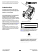
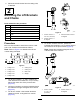
Form No. 3434-368 Rev A 8-Blade or 11-Blade DPA Cutting Unit Reelmaster® 6000-D Series Traction Unit Model No. 03698—Serial No. 404800001 and Up Model No. 03699—Serial No. 404800001 and Up Register at www.Toro.com.
This product complies with all relevant European directives. For details, please see the Declaration of Incorporation (DOI) at the back of this publication. Introduction This cutting unit is designed for cutting grass on well-maintained lawns in golf courses, parks, sports fields, and on commercial grounds. Using this product for purposes other than its intended use could prove dangerous to you and bystanders.
Contents Safety Safety ....................................................................... 3 General Safety ................................................... 3 Cutting Unit Safety.............................................. 3 Blade Safety ....................................................... 4 Safety and Instructional Decals .......................... 4 Setup ........................................................................ 5 1 Removing the Tipper Assemblies.....................
• Inspect the blade periodically for wear or damage. • Keep all parts in good working condition and all hardware tightened. Replace all worn or damaged decals. • Use care when checking the blades. Wrap the blades or wear gloves, and use caution when servicing the blades. Only replace or sharpen the blades; never straighten or weld them. • Use only accessories, attachments, and replacement parts approved by Toro. • On multi-bladed machines, take care as rotating 1 blade can cause other blades to rotate.
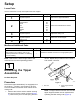
Setup Loose Parts Use the chart below to verify that all parts have been shipped. Procedure Description 1 No parts required 2 Lift chain Chain bracket U-bolt Nut Screw Washer Nut 3 4 5 Use Qty. – 5/7 5/7 5/7 10/14 5/7 5/7 5/7 Remove the tipper assemblies. Mount the lift brackets and chains. No parts required – Adjust the cutting unit No parts required – Mount the counterweights. Large O-ring Screw 5/7 2 Install the cutting units. Media and Additional Parts Description Qty.
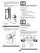
2. Disconnect the lift chains from the cutting units, if attached. 2 Mounting the Lift Brackets and Chains Parts needed for this procedure: 5/7 Lift chain 5/7 Chain bracket 5/7 U-bolt 10/14 g020546 Nut 5/7 Screw 5/7 Washer 5/7 Nut Figure 5 1. Lift arm number 5 = 38.1 cm (15 inches) 3. Lift arm numbers 1 and 5 = 10 degrees 2. Lift arm number 4 = 10 degrees Procedure 4. Mount a chain bracket to each lift arm with a U-bolt and 2 nuts.
5. On lift arm number 6 and number 7, position the brackets and U-bolts 36.8 cm (14.5 inches) behind the center line of the pivot knuckle (Figure 7). 3 Adjusting the Cutting Unit Note: Rotate the brackets 10 degrees to the outboard side of the machine. No Parts Required Procedure 1. Adjust the bedknife to the reel. 2. Adjust the rear roller for your height-of-cut requirements. 3. Set the height of cut. 4. Adjust the rear shield if necessary.
1. 5. On cutting unit numbers 2, 4, and 6, remove the 2 cap screws securing the counterweight to the left end of the cutting unit. Loosely install the 2 reel motor mounting cap screws to the left side plate of the cutting unit (Figure 11). Note: Remove the counterweight (Figure 10). 5 Installing the Cutting Units Parts needed for this procedure: 5/7 2 Large O-ring Screw Procedure 1. Insert a thrust washer onto the horizontal shaft of the pivot knuckle as shown in Figure 12. g003320 Figure 10 1.
8. Secure the lift arm chain to the cutting unit chain bracket (Figure 13) with the snapper pin as follows: • On cutting unit numbers 1, 4, 5, 6, and 7, use only 6 of the chain links. • On cutting unit numbers 2 and 3, use all 7 of the chain links. g004127 Figure 14 1. Reel motor Note: If a fixed cutting unit position is required, insert the steering locking pin into the pivot knuckle mounting hole (Figure 12). g006542 Figure 13 1. Lift chain 2. Snapper pin 13. 9.
Product Overview Operation Specifications Refer to your traction unit Operator’s Manual for detailed operation instructions. Before using the cutting unit each day, adjust the bedknife; refer to Adjusting the Bedknife to the Reel (page 11). Test the quality of cut by cutting a test swath before using the cutting unit to ensure that the finished cut is correct.
Prior to mowing each day, or as required, check each cutting unit to verify proper bedknife-to-reel contact. Perform this procedure even when the quality of cut is acceptable. 1. Slowly rotate the reel in a reverse direction, listening for reel-to-bedknife contact. Note: The adjustment knobs have detents corresponding to 0.022 mm (0.0009 inch) bedknife movement for each indexed position. Refer to Adjusting the Bedknife to the Reel (page 11). 2.
5. Insert the 0.05 mm (0.002 inch) shim between the marked reel blade and the bedknife at the point where the blade crosses the bedknife. 6. Turn the right bedbar adjuster clockwise until you feel light pressure (i.e. drag) on the shim, then back off the bedbar adjuster 2 clicks and remove the shim. Note: Adjusting 1 side of the cutting unit affects the other side, the 2 clicks will provide clearance for when the other side is adjusted.
Adjusting the Turf-Compensation Settings The turf-compensation spring transfers the weight from the front to the rear roller. This helps to reduce a wave pattern in the turf, also known as marcelling or bobbing. Important: Make spring adjustments with the cutting unit mounted to the traction unit, pointing straight ahead and lowered to the shop floor. g003324 Figure 20 1. Spacer 3. Side-plate mounting flange 1. 2. Roller bracket 2. 3. 4. 5. 6. 7.
Adjusting the Height of Cut (HOC) ends of roller until the entire roller is parallel to the bedknife. Note: For heights of cut greater than 2.54 cm (1.00 inch) install the High Height-of-Cut Kit. 1. Loosen the locknuts securing the height-of-cut arms to the cutting-unit side plates (Figure 23). g003328 Figure 25 g003326 Figure 23 1. Adjusting screw Important: When set properly, the rear 3.
Height-of-Cut Chart HOC Setting 0.64 cm (0.250 inches) 0.95 cm (0.375 inches ) 1.27 cm (0.500 inches) 1.56 cm (0.625 inches) 1.91 cm (0.750 inches) 2.22 cm (0.875 inches) 2.54 cm (1.000 inches) 2.86 cm (1.125 inches) 3.18 cm (1.250 inches)*+ 3.49 cm (1.375 inches)*+ 3.81 cm (1.500 inches)*+ 4.13 cm (1.625 inches)*+ 4.44 cm (1.750 inches)*+ 4.76 cm (1.875 inches)*+ 5.08 cm (2.000 inches)*+ * The High HOC Kit (Part No. Aggressiveness of Cut No.
Use the following chart to determine which bedknife is best suited for the desired height of cut. Bedknife/Height of Cut Chart Part No. Bedknife Bedknife Lip Height 110-4084 Height of Cut 5.6 mm 6.4 to 12.7 mm (0.220 inch) (0.250 to 0.500 inch) 5.6 mm 6.4 to 12.7 mm 137-0832 EdgeMax® Low HOC (Optional) (0.220 inch) (0.250 to 0.500 inch) 120-1640 5.6 mm 6.4 to 12.7 mm Extended Low HOC (Optional) (0.220 inch) (0.250 to 0.500 inch) 5.6 mm 6.4 to 12.7 mm 119-4280 Extended EdgeMax® Low HOC (Optional) (0.
Height-of-Cut Chart Terms Height-of-Cut Setting (HOC) This corresponds to the desired height of cut. Bench-Set Height of Cut This is the height at which the top edge of the bedknife is set above a flat level surface that contacts the bottom of both the front and rear rollers. g006502 Figure 27 Effective Height of Cut 1. Rear spacers 3. Aggressiveness of cut 2. Side-plate mounting flange This is the actual height that the grass has been cut.
Maintenance Lubricating the Cutting Unit Each cutting unit has 6 grease fittings (Figure 29) that must be lubricated regularly with No. 2 lithium grease. Using the Kickstand when Tipping the Cutting Unit The lubrication points include the front roller (2), the rear roller (2), and the reel bearing (2).
Adjusting the Reel Bearings To ensure long life of the reel bearings, periodically check if reel end play exists. You can check and adjust the reel bearings as follows: 1. Loosen the reel-to-bedknife contact by turning the bedknife adjusting knobs (Figure 30) counterclockwise until no contact exists. g003332 Figure 32 1. Setscrew B. g019940 Figure 30 1. Bedknife-adjuster knob 2. 2.
Servicing the Bedknife The bedknife service limits are listed in the following chart. Important: Operating the cutting unit with the bedknife below the service limit may result in poor after-cut appearance and reduce the structural integrity of the bedknife for impacts. Bedknife Service Limit Chart Bedknife Part Bedknife Lip Height* Service Limit* EdgeMax® Low HOC (Optional) 137-0832 5.6 mm (0.220 inch) 6.4 to 12.7 mm (0.250 to 0.500 inch) 10/5 degrees Low HOC (Optional) 110-4084 5.6 mm (0.
Checking the Top Grind Angle Servicing the Bedbar The angle that you use to grind your bedknives is very important. Removing the Bedbar Use the angle indicator (Toro Part No. 131-6828) and the angle-indicator mount (Toro Part No. 131-6829) to check the angle that your grinder produces and then correct for any grinder inaccuracy. 1. Place the angle indicator on the bottom side of the bedknife as shown in Figure 35. 1.
2. Clean the screw threads. 3. Apply anti-seize compound to the screws and install the bedknife to the bedbar as follows (Figure 41): g003335 Figure 39 1. Bedbar bolt 2. Nut 3. Steel washer 4. Nylon washer Assembling the Bedbar 1. Install the bedbar, positioning the mounting ears between the washer and the bedbar adjuster. 2. Secure the bedbar to each side plate with the bedbar bolts (nuts on bolts) and 6 washers. 3. 4.
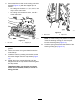
Servicing the HD Dual Point Adjusters (DPA) g279162 Figure 42 1. Bedknife screw tool 3. Torque to 23 to 28 N∙m (200 to 250 in-lb). 2. Install and torque these first to 1 N∙m (10 in-lb). 4. 1. Remove all parts (refer to the Installation Instructions for the HD DPA Kit and to Figure 43). 2. Apply anti-seize compound to the inside of the bushing area on cutting unit center frame (Figure 43). 3. Align the keys on flange bushings to the slots in the frame and install the bushings (Figure 43). 4.
7. Apply anti-seize compound to the threads of the bedbar-adjuster screw that fit into the adjuster shaft. 8. Thread the bedbar-adjuster screw into the adjuster shaft. 9. Loosely install the hardened washer, spring, and spring tension nut onto the adjuster screw. 10. Install the bedbar, positioning the mounting ears between the washer and the bedbar adjuster. 11. Secure the bedbar to each side plate with the bedbar bolts (nuts on bolts) and 6 washers.
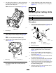
Servicing the Roller inner seals, and outer seals to rebuild a roller. The Roller Rebuild Tool Kit includes all the tools and the installation instructions required to rebuild a roller with the roller rebuild kit. Refer to your parts catalog or contact your authorized Toro distributor for assistance. The Roller Rebuild Kit (Part No. 114-5430) and the Roller Rebuild Tool Kit (Part No. 115-0803) (Figure 44) are available for servicing the roller.
Declaration of Incorporation The Toro Company, 8111 Lyndale Ave. South, Bloomington, MN, USA declares that the following unit(s) conform(s) to the directives listed, when installed in accordance with the accompanying instructions onto certain Toro models as indicated on the relevant Declarations of Conformity. Model No. Serial No.
EEA/UK Privacy Notice Toro’s Use of Your Personal Information The Toro Company (“Toro”) respects your privacy. When you purchase our products, we may collect certain personal information about you, either directly from you or through your local Toro company or dealer.
The Toro Warranty Two-Year or 1,500 Hours Limited Warranty Conditions and Products Covered Parts The Toro Company and its affiliate, Toro Warranty Company, pursuant to an agreement between them, jointly warrant your Toro Commercial product (“Product”) to be free from defects in materials or workmanship for 2 years or 1,500 operational hours*, whichever occurs first. This warranty is applicable to all products with the exception of Aerators (refer to separate warranty statements for these products).