Form No. 3370-629 Rev A 27-inch 8-Blade Cutting Unit Reelmaster® 7000-D Traction Unit Model No. 03710—Serial No. 312000001 and Up Model No. 03711—Serial No. 312000001 and Up Model No. 03712—Serial No. 312000001 and Up To register your product or download an Operator's Manual or Parts Catalog at no charge, go to www.Toro.com.
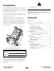
Introduction Figure 2 1. Safety alert symbol Read this information carefully to learn how to operate and maintain your product properly and to avoid injury and product damage. You are responsible for operating the product properly and safely. This manual uses 2 other words to highlight information. Important calls attention to special mechanical information and Note emphasizes general information worthy of special attention. You may contact Toro directly at www.Toro.
Safety shoes and a helmet is advisable and required by some local ordinances and insurance regulations. • Remove all debris or other objects that might be picked up and thrown by the cutting unit reel blades. Keep all bystanders away from the working area. Hazard control and accident prevention are dependent upon the awareness, concern, and proper training of the personnel involved in the operation, transport, maintenance, and storage of the machine.
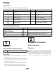
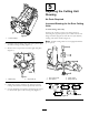
Setup Loose Parts Use the chart below to verify that all parts have been shipped. Procedure Description 1 2 3 4 5 Use Qty. Cutting unit 1 Inspect the cutting unit No parts required – Use the kickstand when tipping the cutting unit No parts required – Adjust the rear shield No parts required – Mount the counter weights No parts required – Adjust the cutting unit steering Media and Additional Parts Description Use Qty.
Figure 3 Figure 4 1. Cutting unit kickstand 1. Rear shield 3 2. Cap screw 4 Adjusting the Rear Shield Mount the Counter Weights No Parts Required No Parts Required Procedure Procedure Under most conditions, best dispersion is attained when the rear shield is closed (front discharge). When conditions are heavy or wet, rear shield may be opened. All cutting units are shipped with the counter weight mounted to the left end of the cutting unit.
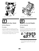
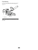
5 Adjusting the Cutting Unit Steering No Parts Required Increased Steering for the Rear Cutting Units 27 inch cutting units only Increase the steering on the rear cutting units by removing the (2) pivot spacers, hex socket screws and flange lock nuts (Figure 8) from the rear (#2 and #3) cutting unit carrier frames (Figure 9). Figure 6 1. Counter weight Note: 32 inch cutting units are not equipped with the pivot spacers. 2.
Fixed Steering To lock (fix) the steering on the cutting units, secure the pivot yoke to the carrier frame with the snapper pin (Figure 10). 1 G015977 Figure 10 1. Snapper pin Note: Fixed steering is recommended when cutting side hills.
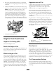
Product Overview Specifications Weight Scrapers (Wiehle, Shoulder, Rear roller, Full Front Roller): Fixed scrapers for all optional rollers are available for reducing grass build up on rollers which can affect height of cut settings. Roller Rebuild Kit: Includes all the bearings, bearing nuts, inner seals and outer seals required to rebuild a roller. Roller Rebuild Tool Kit: Includes all the tools and the installation instructions required to rebuild a roller with the roller rebuild kit.
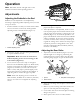
Operation Note: Determine the left and right sides of the machine from the normal operating position. Adjustments Adjusting the Bedknife to the Reel G003323 Bedknife to reel adjustment is accomplished by loosening or tightening bedbar adjusting screws, located on top of mower. Figure 12 4. Check for light contact at other end of reel using paper and adjust as required. 5.
Aggressiveness of Cut 6. Re-secure roller bracket and spacers to underside of side plate mounting flanges with nuts previously removed. Cutting unit Aggressiveness of Cut has a significant impact on the performance of the cutting unit. Aggressiveness of Cut refers to the angle of the bedknife relative to the ground (Figure 15). 7. Verify that bedknife to reel contact is correct. Tip mower to expose front and rear rollers and bedknife.
Important: Make spring adjustments with the cutting unit mounted to the traction unit, pointing straight ahead and lowered to the shop floor. 1. Make sure the hairpin cotter is installed in the rear hole in the spring rod (Figure 16). Note: When servicing the cutting unit, move the hairpin cotter to the spring rod hole next to the turf compensation spring. Figure 17 1. Lift chain 2. U Bracket 3.
Height of Cut Chart HOC Setting Aggressiveness of Cut No. of Rear Spacers No. of Chain Links 5+ Less 0 5+ Normal 0 5+ More 1 5+ 0.375" Less 0 5+ Normal 1 5+ More 2 0.500" Less 0 6 Normal 1 5+ More 2 5+ 0.625" Less 1 6 Normal 2 5+ More 3 5+ 0.750" Less 2 6 Normal 3 5+ More 4 6 0.875" Less 2 6 Normal 3 6 More 4 5+ 1.000" Less 3 6 Normal 4 5+ More 5 5+ 1.125" Less 4 6 Normal 5 5 More 6 5 1.250" Less 4 6 Normal 5 6 More 6 6 1.375" Less 4 6 Normal 5 6 More 6 6 5 6 1.500" Less 6 6 Normal 7 6 More 5 Less 6 1.
Adjusting the Height of Cut 1. Loosen locknuts securing height-of-cut arms to cutting unit side plates (Figure 18). Figure 20 Figure 18 8 Blade Cutting Unit Shown 1. Adjusting screw Important: When set properly, the rear and front rollers will contact the gauge bar and the screw will be snug against the bedknife. This ensures that the height-of-cut is identical at both ends of the bedknife. 3. Height-of-cut arm 2. Locknut 2.
Use the following chart to determine which bedknife is best suited for the desired height of cut. turn the bedknife adjusting knobs clockwise, one click at a time, until light contact is felt and heard. Note: The reel must cut one sheet of paper, when inserted at a right angle to the bedknife, at both ends and the center of the reel. Bedknife/Height of Cut Chart Bedknife Part No. Low HOC (Optional) 120–1641 (27 inch) 120–1642 (32 inch) EdgeMax® (Optional) Bedknife Lip Height .220* inch (5.
Servicing Bedknife The bedknife service limits are listed in the following charts. Important: Operating the cutting unit with the bedknife below the “service limit” may result in poor after-cut appearance and reduce the structural integrity of the bedknife for impacts. Bedknife Service Limit Chart Bedknife Part No. Low HOC (Optional) 120–1641 (27 inch) 120–1642 (32 inch) EdgeMax® (Optional) Bedknife Lip Height * .220 inch (5.6 mm) Service Limit* .190 inch (4.
Maintenance Lubrication Each cutting unit has (6) grease fittings (Figure 25) that must be lubricated regularly with No. 2 General Purpose Lithium Base Grease. Figure 26 The lubrication points are front roller (2), rear roller (2) and reel bearing (2). 1. Bedknife adjusting knob Note: Lubricating cutting units immediately after washing helps purge water out of bearings and increases bearing life. 2.
Note: Reel bearings do not require preload. Over tightening reel bearing adjuster nut will damage reel bearings. 4. Retighten set screw securing bearing adjusting nut to bearing housing. Torque to 12-15 in-lb (1.5-1.7 N-m). Servicing the Bedbar Removing the Bedbar 1. Turn bedbar adjuster screws, counterclockwise, to back bedknife away from reel (Figure 29). Figure 31 1. Bedbar bolt 2. Nut 3. Steel washer 4. Nylon washer Assembling the Bedbar 1.
Servicing the HD Dual Point Adjusters (DPA) 4. Install a wave washer onto the adjuster shaft and slide the adjuster shaft into the flange bushings in the cutting unit frame (Figure 33). 1. Remove all parts (refer to Installation Instructions for HD DPA Kit Model No. 120–7230 and to Figure 33). 5. Secure the adjuster shaft with a flat washer and lock nut (Figure 33). Torque the lock nut to 15 to 20 ft-lb (20 to 27 N-m). 2.
Servicing the Roller outer seals to rebuild a roller. The Roller Rebuild Tool Kit includes all the tools and the installation instructions required to rebuild a roller with the roller rebuild kit. Refer to your parts catalog or contact your distributor for assistance. A Roller Rebuild Kit, Part No. 114–5430 and a Roller Rebuild Tool Kit, Part No. 115–0803 (Figure 34) are available for servicing the roller. The Roller Rebuild Kit includes all the bearings, bearing nuts, inner seals and Figure 34 1.
The Toro Total Coverage Guarantee A Limited Warranty Conditions and Products Covered The Toro® Company and its affiliate, Toro Warranty Company, pursuant to an agreement between them, jointly warrant your Toro Commercial product (“Product”) to be free from defects in materials or workmanship for two years or 1500 operational hours*, whichever occurs first. This warranty is applicable to all products with the exception of Aerators (refer to separate warranty statements for these products).