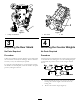
Form No. 3376-921 Rev C 27 and 32-inch Cutting Unit Reelmaster® 7000-D Traction Unit Model No. 03710—Serial No. 313000001 and Up Model No. 03711—Serial No. 313000001 and Up Model No. 03712—Serial No. 313000001 and Up Register at www.Toro.com.
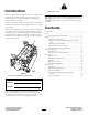
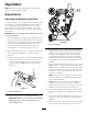
Figure 2 Introduction 1. Safety alert symbol Read this information carefully to learn how to operate and maintain your product properly and to avoid injury and product damage. You are responsible for operating the product properly and safely. This manual uses 2 other words to highlight information. Important calls attention to special mechanical information and Note emphasizes general information worthy of special attention. You may contact Toro directly at www.Toro.
Safety is advisable and required by some local ordinances and insurance regulations. Hazard control and accident prevention are dependent upon the awareness, concern, and proper training of the personnel involved in the operation, transport, maintenance, and storage of the machine. Improper use or maintenance of the machine can result in injury or death. To reduce the potential for injury or death, comply with the following safety instructions.
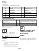
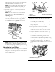
Setup Loose Parts Use the chart below to verify that all parts have been shipped. Procedure Description 1 2 3 4 5 Use Qty. Cutting unit 1 Inspect the cutting unit. No parts required – Use the kickstand when tipping the cutting unit. No parts required – Adjust the rear shield. No parts required – Mount the counter weights. No parts required – Adjust the cutting unit steering. Media and Additional Parts Description Use Qty.
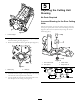
Figure 3 Figure 4 1. Cutting unit kickstand 1. Rear shield 2. Bolt 4 3 Adjusting the Rear Shield Mounting the Counter Weights No Parts Required No Parts Required Procedure Procedure Under most conditions, the best dispersion is attained when the rear shield is closed (front discharge). When conditions are heavy or wet, rear shield may be opened. All cutting units are shipped with the counter weight mounted to the left end of the cutting unit.
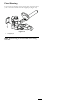
5 Adjusting the Cutting Unit Steering No Parts Required Increased Steering for the Rear Cutting Units Increase the steering on the rear cutting units by removing the 2 pivot spacers, hex socket screws and flange lock nuts (Figure 8) from the rear (#2 and #3) cutting unit carrier frames (Figure 9). Figure 6 1 1. Counter weight 3. On right end of cutting unit, remove the plastic plug from the bearing housing (Figure 7). 2 4. Remove the 2 bolts from the right side plate (Figure 7).
Fixed Steering To lock (fix) the steering on the cutting units, secure the pivot yoke to the carrier frame with the snapper pin (Figure 10). 1 G015977 Figure 10 1. Snapper pin Note: Fixed steering is recommended when cutting side hills.
Product Overview Specifications. Weight Collar Kit (6 per needed per roller): Helps reduce over lap marks for warm season grasses (Bermuda, Zoysia, Paspalum). This kit is installed on the existing Wiehle roller, but is not as aggressive as the Shoulder roller. Short Rear Roller: Helps reduce double roller marks for cool season grasses (Bent, Blue grass, Rye).
Operation Note: Determine the left and right sides of the machine from the normal operating position. Adjustments Adjusting the Bedknife to the Reel Use this procedure to set the bedknife to the reel and to check the condition of the reel and bedknife and their interaction. After completing this procedure, always test the cutting unit performance under your field conditions. You may need to make further adjustments to obtain optimal cutting performance.
sides prevents the shim from passing through on both sides. The bedknife is now parallel to the reel. Note: This procedure should not be needed on daily adjustments, but should be done after grinding or disassembly. 9. From this position (i.e. one click in and shim not passing through) turn the bedbar adjusters clockwise one click each. Figure 14 Note: Each click turned moves the bedknife 0.022 mm (0.0009 inches). Do not over tighten the adjusting screws. 1. Spacer 3. Side plate mounting flange 2.
Rear Spacers Height-of-Cut Chart Terms The number of rear spacers determines the aggressiveness of cut for the cutting unit. For a given height of cut, adding spacers, below the side plate mounting flange, increases the aggressiveness of the cutting unit. All cutting units on a given machine must be set to the same aggressiveness of cut (Number of rear spacers, part no. 106-3925), otherwise the after-cut appearance could be negatively affected (Figure 16).
Chain Links The location at which the lift arm chain is attached determines the rear roller pitch angle (Figure 18). Figure 18 1. Lift chain 2. U Bracket 3.
Groomer The following chart shows the recommended height of cut settings when a groomer kit is installed on the cutting unit. Height of Cut Chart HOC Setting Aggressiveness of Cut No. of Rear Spacers No. of Chain Links With Groomer kits installed 0.64 cm (0.
4.13 cm (1.625 inches) * 4.44 cm (1.750 inches) * 4.76 cm (1.875 inches) * 5.08 cm (2.000 inches) * 5.40 cm (2.125 inches) * 5.71 cm (2.250 inches) * 6.03 cm (2.375 inches) * 6.35 cm (2.
Adjusting the Height of Cut 1. Loosen locknuts securing height-of-cut arms to cutting unit side plates (Figure 19). Figure 21 Figure 19 8-blade cutting unit shown 1. Adjusting screw Important: When set properly, the rear and front rollers will contact the gauge bar and the screw will be snug against the bedknife. This ensures that the height-of-cut is identical at both ends of the bedknife. 3. Height-of-cut arm 2. Locknut 2.
edge surface along the full length of the bedknife. If a file is occasionally run across the front edge to remove this burr, improved cutting can be obtained. After extended running, a ridge will eventually develop at both ends of the bedknife. These notches must be rounded off or filed flush with the cutting edge of the bedknife to ensure smooth operation. Figure 22 1.
Servicing The Bedknife The bedknife service limits are listed in the following charts. Important: Operating the cutting unit with the bedknife below the service limit may result in poor after-cut appearance and reduce the structural integrity of the bedknife for impacts. Bedknife Service Limit Chart Bedknife Part No. Bedknife Lip Height Service Limit* Grind Angles Top/Front Angle Low HOC (Optional) 120–1641 (27 inch) 120–1642 (32 inch) 5.6 mm (.220 inch) 4.8 mm (.
Maintenance 2. Using a rag or thickly padded glove, hold on to the reel blade and try to move the reel assembly side to side (Figure 28). Lubrication Each cutting unit has 6 grease fittings (Figure 26) that must be lubricated regularly with No. 2 general purpose, lithium-base grease. The lubrication points are front roller (2), rear roller (2), and reel bearing (2). Note: Lubricating cutting units immediately after washing helps purge water out of bearings and increases bearing life. 1.
Servicing the Bedbar Removing the Bedbar 1. Turn bedbar adjuster screws, counterclockwise, to back bedknife away from reel (Figure 30). Figure 32 1. Bedbar bolt 2. Nut 3. Steel washer 4. Nylon washer Assembling the Bedbar 1. Install the bedbar, positioning the mounting ears between the washer and bedbar adjuster. Figure 30 1. Bedbar adjusting screw 3. Bedbar 2. Spring tension nut 4. Washer 2. Secure bedbar to each side plate with bedbar bolts (nuts on bolts) and 6 washers. 3. 2.
Servicing the HD Dual Point Adjusters (DPA) 4. Install a wave washer onto the adjuster shaft and slide the adjuster shaft into the flange bushings in the cutting unit frame (Figure 34). 1. Remove all parts (refer to Installation Instructions for HD DPA Kit Model No. 120–7230 and to Figure 34). 5. Secure the adjuster shaft with a flat washer and lock nut (Figure 34). Torque the lock nut to 20 to 27 N-m (15 to 20 ft-lb). 2.
Servicing the Roller bearings, bearing nuts, inner seals and outer seals to rebuild a roller. The Roller Rebuild Tool Kit includes all the tools and the installation instructions required to rebuild a roller with the roller rebuild kit. Refer to your parts catalog or contact your Authorized Toro Distributor for assistance. A Roller Rebuild Kit, Part No. 114–5430 and a Roller Rebuild Tool Kit, Part No. 115–0803 (Figure 35) are available for servicing the roller.
Notes: 22
Declaration of Incorporation The Toro Company, 8111 Lyndale Ave. South, Bloomington, MN, USA declares that the following unit(s) conform(s) to the directives listed, when installed in accordance with the accompanying instructions onto certain Toro models as indicated on the relevant Declarations of Conformity. Model No. Serial No.
The Toro Total Coverage Guarantee A Limited Warranty Conditions and Products Covered Parts The Toro® Company and its affiliate, Toro Warranty Company, pursuant to an agreement between them, jointly warrant your Toro Commercial product (“Product”) to be free from defects in materials or workmanship for two years or 1500 operational hours*, whichever occurs first. This warranty is applicable to all products with the exception of Aerators (refer to separate warranty statements for these products).