Form No. 3392-136 Rev A Right/Left-Hand Groomer Kit 27-inch Reelmaster® 7000-D DPA Cutting Unit Model No. 03713 Model No. 03714 Register at www.Toro.com.
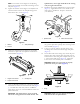
WARNING CALIFORNIA Proposition 65 Warning This product contains a chemical or chemicals known to the State of California to cause cancer, birth defects, or reproductive harm. The engine exhaust from this product contains chemicals known to the State of California to cause cancer, birth defects, or other reproductive harm. Figure 1 1. Safety alert symbol This manual uses 2 other words to highlight information.
Contents Safety Safety ........................................................................... 3 Safe Operating Practices........................................... 3 Setup ............................................................................ 5 Tools Required for Setup .......................................... 5 Installing the Groomer............................................. 6 Installing the Broomer Kit (optional).........................17 Operation .......................................
genuineness. Using unapproved replacement parts and accessories could void the warranty of The Toro® Company.
Setup Loose Parts Use the chart below to verify that all parts have been shipped. Description Use Qty. 45 degree grease fitting Height of cut bracket assembly, R.H. Height of cut bracket assembly, L.H.
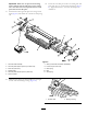
Groomer Kit Orientation All cutting units are shipped with the counter weight mounted to the left end of the cutting unit. Use the following diagram to determine the position of the groomer kits and reel motors. Figure 2 Figure 3 1. Counter weight Note: These instructions and illustrations show the installation of the Left Hand Groomer Kit onto the cutting units with the counter weights mounted on the left end of the cutting unit.
Note: The washers on the height of cut adjusting bolts must be located on each side of the flange on the side plate (Figure 5). splined insert, on the right hand side of the cutting unit, has right hand threads. 13. Install the new (longer) splined insert to the reel shaft (Figure 7). Apply blue Loctite to the threads of the insert prior to installation. Torque to 85-95 ft-lb (115–129 N-m). 10.
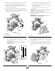
Important: Make sure the pivot hub mounting surface is flush with the side plate on the cutting unit. The shim must not be pinched between the pivot hub and the side plate. 18. Secure the non-drive pivot hub to the cutting unit side plate with (2) 3/8 x 1 inch socket head screws (Figure 9). Apply blue Loctite to the screw threads prior to installation. 17. Install the non-drive groomer plate onto the groomer shaft (Figure 9). Be careful not to knock the seal spring off. Figure 9 1.
20. Mount the quick-up lever assemblies to the side plates with 3/8 x 3/4 inch flange head bolts (Figure 9). • The outer faces of the drive and driven pulleys 21. Install the groomer belt onto the pulleys (Figure 9). Make sure the ribs on the belt are properly seated in the grooves on each pulley. • • 22. Hook the idler spring in the hole in the idler plate tab and around the groove on the groomer plate lower stud (Figure 11). The open end of the spring hook is to be positioned toward the drive pulley.
Note: After greasing groomer bearings, operate groomer for 30 seconds, stop machine and wipe excess grease from groomer shaft and seals. idler pulley to the roller brush pivot plate. Do not remove the nut. 5. Remove the bolt securing the roller brush drive pulley to the bearing housing shaft (Figure 16). 27. Adjust the height of the groomer. Refer to Adjusting Groomer Height. 6. Remove the roller brush drive pulley and the spacer from the shaft (Figure 16).
Figure 20 Figure 18 1. Height of cut bracket 1. Bearing housing 3. Carriage bolt 2. Capscrew & locknut 12. Remove the carriage bolts and nuts securing the height of cut brackets to the cutting unit side plates (Figure 19). 16. Using the upper square hole in each side plate, loosely mount the height of cut brackets to the cutting unit side plates with the carriage bolts previously removed and new 3/8 inch flange nuts, positioning as shown in figure Figure 20. 13.
Clean all the grease out of the threaded hole where the splined insert was. Important: The splined insert on the left hand side of the cutting unit has left hand threads. The splined insert, on the right hand side of the cutting unit, has right hand threads. Figure 23 1. O-ring Important: Make sure the splined end of pivot hub shaft fits into the splined insert. Important: Make sure the pivot hub mounting surface is flush with the side plate on the cutting unit.
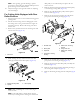
Figure 24 1. Groomer shaft assembly 7. Shim (must remain loose after installation) 2. Groomer plate w/quick-up lever (non-drive end) 8. Pivot hub (non-drive end) 9. Idler spring 3. Pivot hub (drive end) 4. Splined shaft 10. Belt 5. Groomer plate w/quick-up lever (drive end) 11. Seal spring 6. Quick-up lever 25. Secure the non-drive pivot hub to the cutting unit side plate with (2) 3/8 x 1 inch screws (Figure 24). Apply blue Loctite to the screw threads prior to installation. 28.
31. Remove the (2) 5/16 inch flange nuts securing the groomer weight to the groomer cover and remove the weight (Figure 28). Figure 26 1. Idler spring Figure 28 3. Lower stud 2. Idler plate tab 1. Groomer weight 2. Groomer cover 5. Cover screws (remove) 30. Check the alignment of the belt/pulleys as follows: 3. Solid grommet 6. Set screw (2) 4. Rubber grommet ring • Lay a straight edge along the outer face of the drive pulley (Figure 27). 32.
the pulley tabs are positioned in the slot in the drive shaft. 36. Apply a film of grease to the inside diameter of the grommet in the groomer cover (Figure 29). 44. Apply Loctite to the threads of the 3/8 x 2 inch flange head bolt. Secure the drive pulley to the shaft with the flange head bolt (Figure 31). Torque the bolt to 34-40 ft-lb (46–54 N-m). 37. Loosen the bolts securing the roller brush bearing housing to the roller brush mounting bracket (Figure 30). 38.
46. Push down on the idler pulley to ensure that the idler pulley assembly pivots freely. 47. Check the alignment of the belt/pulleys as follows: • Lay a straight edge along the outer face of the drive pulley (Figure 33). G011429 Figure 35 G011428 50. Grease each of the groomer bearings (2 or 3 pumps maximum) (Figure 35). Do not over-grease as excess grease may cause seal failure. Wipe off any excess grease.
Installing the Broomer Kit (optional) 1. From one side of the groomer reel, slide a brush into each groove around the full length of the groomer reel (Figure 36). Figure 36 1. Brush 2. Strap 2. Verify that the brushes are seated in the groomer blade slots (Figure 37 & Figure 38). 3.
Operation • The height/depth setting on the grooming reel Grooming is performed in the turf canopy above the soil level. Grooming promotes vertical growth of grass plants, reduces grain and severs stolons producing a denser turf. Grooming produces a more uniform and tighter playing surface for faster and truer action of the golf ball. • The type of grass Verticutting is a more aggressive cultivation technique designed to remove thatch by cutting through the turf canopy and into the thatch/mat layer.
Figure 40 1. Quick-up lever (engaged position) 3. Height adjuster knob 2. Groomer height (HOG) 4. Number of rear roller spacers (below side plate pad) 5. Repeat step 4 on the opposite end of the groomer. Then, recheck the setting on the first side of groomer. Height setting on both ends of the groomer should be identical. Readjust as required. Important: After adjusting the height of the groomer, adjust the jam nuts on threaded rod, so the springs are 1-3/8 inch (3.
Height of Cut (HOC) and Height of Groom (HOG) Recommended Range Height of Cut Number of Rear Roller Spacers Recommended HOG = HOC- Groomer Engagement .250 inch (6.4 mm) 0 .125-.250 (3.1–6.4 mm) .375 inch (9.5 mm) .375 inch (9.5 mm) 0 1 .187-.375 (4.7–9.5 mm) .187-.375 (4.7–9.5 mm) .500 inch (12.7 mm) .500 inch (12.7 mm) .500 inch (12.7 mm) 0 1 2 .250-.500 (6.4–12.7 mm) .250-.500 (6.4–12.7 mm) .250-.375 (6.4–9.5 mm) .625 inch (15.8 mm) .625 inch (15.8 mm) .625 inch (15.8 mm) 0 1 2 .375-.625 (9.
Maintenance 2. Remove idler spring, releasing tension from the belt. Remove the belt. Cleaning 3. Remove the lock nut securing the driven pulley to the end of the groomer shaft. Insert a 5/8 inch wrench on the flats on the groomer shaft to keep the shaft from rotating. Hose off the grooming reel after using it. Do not direct the water stream directly at the groomer bearing seals. Do not permit the grooming reel to stand in water so that the components rust. 4. Remove the pulley from the shaft. 5.
Groomer Binding Troubleshooting 5. If a roller brush is installed, make sure the brush plate (Figure 46) is parallel to the cutting unit side plate and is fully inserted into the rubber grommets. 1. Make sure the groomer is set to the desired height of groom (HOG) (Figure 44). G011430 1 Figure 46 1. Brush plate 6. Make sure the main drive bushing (Figure 47) pivots freely around the drive hub. Figure 44 1. Quick-up lever (engaged position) 3. Height adjuster knob 2. Groomer height (HOG) 4.
Figure 48 1. Shim 8. Make sure nuts on groomer and roller brush covers (Figure 49) are not over tightened. Figure 49 1.
Declaration of Incorporation Model No. Serial No.