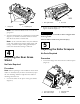
Form No. 3366-458 Rev A 27-inch Heavy-Duty Verticutter Reelmaster® 7000-D DPA Cutting Unit Model No. 03716—Serial No. 311000001 and Up To register your product or download an Operator's Manual or Parts Catalog at no charge, go to www.Toro.com.
Contents Introduction Introduction................................................................. 2 Safety ........................................................................... 3 Safety and Instructional Decals ............................. 3 Setup............................................................................ 4 1 Inspecting the Verticutter................................... 5 2 Installing the Transport Rollers .......................... 5 3 Adjusting the Blade Depth .................
Safety clothing which could get caught in moving parts. Always wear long pants and substantial shoes. Wearing safety glasses, safety shoes and a helmet is advisable and required by some local ordinances and insurance regulations. Hazard control and accident prevention are dependent upon the awareness, concern, and proper training of the personnel involved in the operation, transport, maintenance, and storage of the machine. Improper use or maintenance of the machine can result in injury or death.
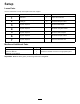
Setup Loose Parts Use the chart below to verify that all parts have been shipped. Procedure 1 2 3 4 5 6 7 Description Use Qty. Verticutter 1 Inspect the verticutter Transport roller assembly Cotter pin 2 2 Install the transport rollers. No parts required – Adjust the blade depth. No parts required – Adjust the rear grass shield. No parts required – Adjust the roller scrapers. No parts required – Adjust the transport rollers.
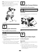
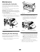
Note: Determine the left and right sides of the machine from the normal operating position. 2 Note: Whenever the verticutter has to be tipped to expose the verticutter blades, use the kick stand (supplied with traction unit) (Figure 2). Installing the Transport Rollers Parts needed for this procedure: 2 Transport roller assembly 2 Cotter pin Procedure Secure a transport roller bracket to each side plate pin with a cotter pin (Figure 3). Figure 2 1. Kick stand 1 Figure 3 1.
2 Figure 5 1 G012693 1. Rear grass shield 2. Pivot bolt Figure 4 1. Gauge bar 2. Adjusting bolt 2. Rotate the grass shield to the desired setting, and tighten the bolts (Figure 5). Note: The verticutter blades must not touch the gauge bars. CAUTION Do not open the rear shield so that it is higher than level to ground. 3. Turn the adjusting bolt on each height-of-cut bracket (Figure 4) so that the reel blades come in contact with the level surface on both ends.
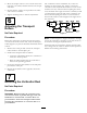
The verticutters can be installed at any of the five locations on the traction unit. Figure 7 shows the orientation of the hydraulic drive motor for each of the locations. For any of the locations requiring the motor to be mounted on the right end of the verticutter, install a counterweight on the left end of the verticutter. For the locations requiring the motor to be mounted on the left end, install a counterweight on the right end of the verticutter. 2. Move the scraper rods in or out to attain 0.
Product Overview Operation Specifications Note: Determine the left and right sides of the machine from the normal operating position. Net Weight 158 lb. (72 kg) Training Period Before operating the verticutter reels, evaluate the performance of the reel at the desired setting. Operate in a clear, unused area to determine if the desired results will be achieved. Adjust as desired. Operating Tips 1. Operate the traction unit at full throttle, full reel speed (setting 9) and at desired traction speed.
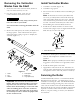
Maintenance Lubricating the Verticutter Each verticutter has 6 grease fittings (Figure 8) that must be lubricated weekly with No. 2 General Purpose Lithium Base Grease. The lubrication points are the front roller (2), the rear roller (2) and the reel bearings (2). 1 Important: Lubricating cutting units immediately after washing helps purge water out of bearings and increases bearing life. G012694 Figure 9 1. Reel shaft 1. Wipe each grease fitting with a clean rag. 2.
Removing the Verticutter Blades from the Shaft Install Verticutter Blades 1. Secure the end of the verticutter shaft, which has only one washer and nut, in a vise. 2. Assemble a large spacer. 1. Assemble a reel blade (Figure 12). 3. Do not invert the reel blades when reassembling on reel shaft. 2. On other end of shaft, rotate the nut counter-clockwise and remove the nut.
Figure 13 1. 2. 3. 4. 5. 6. 7. 8. 9. Rebuild kit (Part No. 114–5430) Rebuild tool kit (Part No.
The Toro Total Coverage Guarantee A Limited Warranty Conditions and Products Covered The Toro® Company and its affiliate, Toro Warranty Company, pursuant to an agreement between them, jointly warrant your Toro Commercial product (“Product”) to be free from defects in materials or workmanship for two years or 1500 operational hours*, whichever occurs first. This warranty is applicable to all products with the exception of Aerators (refer to separate warranty statements for these products).