Form No. 3407-868 Rev A 8 and 11-Blade 27-inch and 8-Blade 32-inch Edge Series Cutting Unit Reelmaster® 7000-D Traction Unit Model No. 03721—Serial No. 400000000 and Up Model No. 03722—Serial No. 400000000 and Up Model No. 03727—Serial No. 400000000 and Up Register at www.Toro.com.
which signals a hazard that may cause serious injury or death if you do not follow the recommended precautions. WARNING CALIFORNIA Proposition 65 Warning This product contains a chemical or chemicals known to the State of California to cause cancer, birth defects, or reproductive harm. g000502 Figure 2 1. Safety-alert symbol This product complies with all relevant European directives. For details, please see the Declaration of Incorporation (DOI) at the back of this publication.
Safety advisable and required by some local ordinances and insurance regulations. Secure loose clothing. This machine has been designed in accordance with EN ISO 5395:2013 and ANSI B71.4-2012. • Tie back long hair. Do not wear jewelry. • Remove all debris or other objects that might be picked Improper use or maintenance of this equipment can result in injury or death. To reduce the potential for injury or death, comply with the following safety instructions.
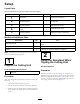
Setup Loose Parts Use the chart below to verify that all parts have been shipped. Procedure Description 1 2 3 4 5 Use Qty. Cutting unit 1 Inspect the cutting unit. No parts required – Use the kickstand when tipping the cutting unit. No parts required – Adjust the rear shield. Straight grease fitting O-ring 1 1 Install the loose parts. No parts required – Adjust the cutting-unit steering. Media and Additional Parts Description Use Qty.
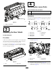
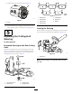
4 Installing the Loose Parts Parts needed for this procedure: 1 Straight grease fitting 1 O-ring Procedure The grease fitting must be installed on the reel-motor side of the cutting unit. Refer to Figure 5 to determine the position of the reel motors. g191340 Figure 3 1. Cutting unit kickstand 3 g031275 Figure 5 Adjusting the Rear Shield No Parts Required 1. Cutting unit 1 5. Cutting unit 5 2. Cutting unit 2 6. Reel motor 3. Cutting unit 3 7. Weight 4. Cutting unit 4 Procedure 1.
4. Install the O-ring on the reel motor (Figure 7). g031275 Figure 9 g191072 Figure 7 1. O-ring 1. Cutting unit 1 5. Cutting unit 5 2. Cutting unit 2 6. Reel motor 3. Cutting unit 3 7. Weight 4. Cutting unit 4 5. Install the reel motor, and grease the side plate until excess grease comes out of the grease vent (Figure 6). Locking the Steering 5 To lock (fix) the steering on the cutting units, secure the pivot yoke to the carrier frame with the snapper pin (Figure 10).
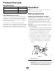
Product Overview Specifications Cutting Unit Operation Weight 27 inch, 8 blade 66 kg (145 lb) 27 inch, 11 blade 68 kg (150 lb) 32 inch, 8 blade 74 kg (162 lb) Note: Determine the left and right sides of the machine from the normal operating position. Making Adjustments Attachments/Accessories Adjusting the Bedknife to the Reel A selection of Toro-approved attachments and accessories is available for use with the machine to enhance and expand its capabilities.
Note: This procedure should not be needed on daily adjustments, but should be done after grinding or disassembly. 10. From this position (i.e., 1 click in and shim not passing through) turn the bedbar adjusters clockwise 1 click each. Note: Each click turned moves the bedknife 0.022 mm (0.0009 inch). Do not overtighten the adjusting screws. 11. Test the cutting performance by inserting a long strip of cutting performance paper (Toro Part No.
3. Remove the 2 nuts securing each roller bracket and spacer to each side-plate mounting flange. soil conditions. The cutting unit setup (aggressiveness of cut, rollers, bedknives, attachments installed, turf compensation settings, etc.) will also affect the effective height of cut. Check the effective height of cut using the Turf Evaluator (Model 04399) regularly to determine the desired bench set height of cut. 4. Lower the roller and screws from the side-plate mounting flanges and spacers. 5.
g020410 Figure 17 1. Lift chain 2. U bracket 3. Bottom hole Groomer These are the recommended height-of-cut settings when a groomer kit is installed on the cutting unit.
Height-of-Cut Chart HOC Setting Aggressiveness of Cut No. of Rear Spacers No. of Chain Links With Groomer Kits Installed 0.64 cm (0.250 inch) Less Normal More 0 0 1 5+ 5+ 5+ Y Y - 0.95 cm (0.375 inch) Less Normal More 0 1 2 5+ 5+ 5+ Y Y - 1.27 cm (0.500 inch) Less Normal More 0 1 2 6 5+ 5+ Y Y Y 1.59 cm (0.625 inch) Less Normal More 1 2 3 6 5+ 5+ Y Y - 1.91 cm (0.750 inch) Less Normal More 2 3 4 6 5+ 6 Y Y - 2.22 cm (0.875 inch) Less Normal More 2 3 4 6 6 5+ Y Y - 2.
Less Normal More 6.35 cm (2.500 inches) 9 10 11 - 6 6 6 + indicates that the U bracket, on the lift arm, is positioned in the bottom hole (Figure 17). "Y" indicates that this combination of HOC and spacers can be used with 27-inch groomers. Note: Changing 1 chain link changes the rear-roller pitch angle movement by 4.5 degrees. Note: Changing the U bracket (Figure 17), on the lift arm to the bottom hole adds 2.3 degrees to the rear-roller pitch angle. Adjusting the Height of Cut (HOC) 3.
Bedknife/Height of Cut Chart Bedknife Part No. Bedknife Lip Height * Height of Cut Low HOC (Optional) 120-1641 (27 inch) 120-1642 (32 inch) 5.6 mm (0.220 inch) 6.4 to 12.7 mm (0.250 to 0.500 inch) EdgeMax® (Optional) 112-8910 (27 inch) 112-8956 (32 inch) 6.9 mm (0.270 inch) 9.5 to 63.5 mm (0.375 to 2.50 inches)* Standard (Production) 114-9388 (27 inch) 114-9389 (32 inch) 6.9 mm (0.270 inch) 9.5 to 63.5 mm (0.375 to 2.50 inches)* 114-9390 (27 inch) 114-9391 (32 inch) 9.3 mm (0.
Note: The adjustment knobs have detents corresponding to 0.022 mm (0.0009 inch) bedknife movement for each indexed position. 3. If excessive contact/reel drag is evident, either backlap, reface the front of the bedknife, or grind the cutting unit to achieve the sharp edges needed for precision cutting; refer to the Toro Manual for Sharpening Reel and Rotary Mowers (Form No. 09168SL). Important: Light contact is preferred at all times.
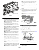
Maintenance Lubricating the Cutting Unit Each cutting unit has 5 grease fittings (Figure 24) that must be lubricated regularly with No. 2 lithium grease. The lubrication points are the front roller (2), the rear roller (2), and at the reel motor spline (1). Note: Lubricating the cutting units immediately after washing helps purge water out of the bearings and increases bearing life. 1. Wipe each grease fitting with a clean rag. 2.
Servicing the Bedknife The bedknife service limits are listed in the following chart. Important: Operating the cutting unit with the bedknife below the service limit may result in poor after-cut appearance and reduce the structural integrity of the bedknife for impacts. Bedknife Service Limit Chart Bedknife Part No. Bedknife Lip Height Service Limit* Grind Angles Top/Front Angles Low HOC (Optional) 120-1641 (27 inch) 120-1642 (32 inch) 5.6 mm (0.220 inch) 4.8 mm (0.
g003334 Figure 31 1. Bedbar bolt 4. Remove each bedbar bolt, allowing the bedbar to be pulled downward and removed from machine bolt (Figure 31). g034114 Figure 29 1. Angle-indicator mount 2. Lock nut 3. Bedknife Note: Account for 2 nylon washers and 1 stamped steel washer on each end of the bedbar (Figure 32). 2. Edge of the magnet mated 4. Angle indicator with the edge of the bedknife 4. Place the angle indicator on the mount as shown in Figure 29.
2 1 g016648 g016648 Figure 33 1. Spring-tension nut 2.
Servicing the HD Dual Point Adjusters (DPA) 3. Align the keys on flange bushings to the slots in the frame and install the bushings (Figure 34). 4. Install a wave washer onto the adjuster shaft and slide the adjuster shaft into the flange bushings in the frame of the cutting unit (Figure 34). 1. Remove all parts (refer to the Installation Instructions for the HD DPA Kit (Model No. 120-7230) and to Figure 34). 5. Secure the adjuster shaft with a flat washer and locknut (Figure 34).
Servicing the Roller nuts, inner seals, and outer seals to rebuild a roller. The Roller Rebuild Tool Kit includes all the tools and the installation instructions required to rebuild a roller with the roller rebuild kit. Refer to your parts catalog or contact your Authorized Toro Distributor for assistance. The Roller Rebuild Kit (Part No. 114-5430) and the Roller Rebuild Tool Kit (Part No. 115-0803) (Figure 35) are available for servicing the roller.
Notes:
Declaration of Incorporation The Toro Company, 8111 Lyndale Ave. South, Bloomington, MN, USA declares that the following unit(s) conform(s) to the directives listed, when installed in accordance with the accompanying instructions onto certain Toro models as indicated on the relevant Declarations of Conformity. Model No. Serial No.
European Privacy Notice The Information Toro Collects Toro Warranty Company (Toro) respects your privacy. In order to process your warranty claim and contact you in the event of a product recall, we ask you to share certain personal information with us, either directly or through your local Toro company or dealer. The Toro warranty system is hosted on servers located within the United States where privacy law may not provide the same protection as applies in your country.
The Toro Warranty A Two-Year Limited Warranty Conditions and Products Covered The Toro Company and its affiliate, Toro Warranty Company, pursuant to an agreement between them, jointly warrant your Toro Commercial product (“Product”) to be free from defects in materials or workmanship for two years or 1500 operational hours*, whichever occurs first. This warranty is applicable to all products with the exception of Aerators (refer to separate warranty statements for these products).