Form No. 3350–280 5, 7, and 11 Blade Cutting Units Reelmaster 4000-D Series Model Model Model Model Model Model No. 03752—230000001 and No. 03753—230000001 and No. 03723—230000001 and No. 03724—230000001 and No. 03725—230000001 and No.
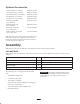
Contents Introduction Page Introduction . . . . . . . . . . . . . . . . . . . . . . . . . . . . . . . . 2 Safety . . . . . . . . . . . . . . . . . . . . . . . . . . . . . . . . . . . . . 3 Safety and Instruction Decals . . . . . . . . . . . . . . . 3 Specifications . . . . . . . . . . . . . . . . . . . . . . . . . . . . . . . 3 General Specifications . . . . . . . . . . . . . . . . . . . . 3 Optional Accessories . . . . . . . . . . . . . . . . . . . . . . 4 Assembly . . . . . . . . . . . . . . . . . . . .
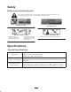
Safety Safety and Instruction Decals Safety decals and instructions are easily visible to the operator and are located near any area of potential danger. Replace any decal that is damaged or lost. Part No. 67-7960 Part No. 85-6410 Part No. 93-6688 (for CE) Part No. 93-7814 (for CE) 1. Danger—read the operator’s manual before performing maintenance. 2. Cutting hazard to hands, fingers, and feet—stop the engine before going near rotating reels. 1. Entanglement hazard—stay away from moving parts.
Optional Accessories Floatation Kit (1 per machine) Model No. 03760 Fixed Head Kit (1 per machine) Model No. 03762 Wiehle Roller Kit (1 per machine) Model No. 03740 Side Skid Kit (1 per machine) Model No. 03744 Full Roller Kit (1 per machine) Model No. 03742 Dethatching Unit, RH (3 per machine) Model No. 03732 Dethatching Unit, LH (2 per machine) Model No. 03730 Rear Roller Scraper Kit (1 per cutting unit) Part No. 59-6090 Front Full Roller Scraper Kit (1 per cutting unit) Part No.
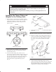
Caution If you leave the key in the ignition switch, someone could accidently start the engine and seriously injure you or other bystanders. Remove the key from the ignition before installing, servicing, or making adjustments to the cutting units. 3 Installing the Tipper Plates and Weights to the Cutting Units 2 1. Refer to Figure 1 and layout all five cutting units on the floor in front of the machine. Position 3 right-hand cutting units (all three are alike) as #1, #3 and #5.
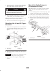
Installing the Floatation Kit 1 2 Mount a Flotation Kit Assembly (Fig. 4) to each cutting unit with U-bolts, lock washers and nuts supplied with kits. Male end of floatation assembly to be positioned forward. Tighten U-bolts evenly. Caution Fingers can be pinched in the floatation u-joint. 5 Keep hands and fingers away from the u-joint. 3 4 Note: When installing floating head assembly to cutting unit, make sure flap on bottom of assembly is positioned to the inside of the cutting frame tubes (Fig.
Mount the Roller Bumpers (Floatation Kit Only) 3. Stop the traction unit and remove the key. Manually pull the lift arms, one at a time, to floor level. Repeat this procedure for the #4 and #5 cutting units. Note: Roller bumpers are required only when operating cutting units in the float position and front rollers are installed. Caution Without the cutting units installed, restarting the engine will result in the lift arms raising. 1. Locate mounting position of roller bumpers (Fig.
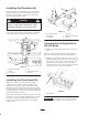
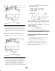
Mounting the Hydraulic Motors to the Cutting Units 3. Insert the reel drive motor pulley through the housing and slip the cutting unit drive belt over the pulley (Fig. 11). 1. Remove locknuts, bolts, shipping cover, and drive plate shield (Fig. 9) from the cutting unit. 1 2 3 Figure 11 1. Hydraulic motor 2. Motor pulley 3. Drive belt 4. Insert the 2 reel drive motor mounting bolts (heads on inside of the drive housing—flat washer on top bolt) through the reel motor flange holes.
hydraulic motors have been mounted and the belts tightened, loosen swivel nuts at the motor and reposition hoses. This can greatly increase the life of the hoses. With cutting units down, all cutting unit hoses should have a flat natural lay and be free from twist. 3. If there is excessive contact, turn the adjusting knobs counterclockwise until no contact is noticed. Then equally turn both adjusting knobs clockwise, until light contact is felt and heard between the reel and bedknife.
contact after the jam nuts have been tightened. Check roller contact by trying to slide paper between the roller and the flat surface. 1 2 3/8 Figure 14 Cutting Unit Float Position 1. Lockout pin 2. Jam nut 2. Insert a piece of bar stock 25–28 in. (70 cm) long (Fig. 16), and approximately 3/8 in. (9.5 mm) thicker than the desired height-of-cut, under the reel and up against the bedknife cutting edge (Fig. 16). The reel (not bedknife) must contact the bar stock along its full length.
4. Loosen front roller nuts and adjust both ends of the front roller until it contacts gauge bar at both ends. With the gauge bar held firmly against the bottom of the rollers, adjust the front roller so the screw head just slips over the lip of the bedknife (Fig. 19). Tighten the front roller nuts. 2 1 Figure 17 1. Long cone nut 98-1852 2. Short cone nut 3. Loosen the gauge bar jam nut and adjust the first screw to set dimension between underside of screw head and gauge bar for desired height-of-cut.
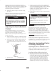
3 Checking/Adjusting the Cutting Unit Attitude 4 1. Place an angle indicator, Toro Part No. 99-3503, on the bedknife and record the bedknife angle (Fig. 20). 1 1 2 Figure 21 1. First screw 2. Second screw 3. Gauge bar angle 4. Front roller Figure 20 4. Adjust the second screw to contact the bedknife. 1. Bedknife angle 5. Place an angle indicator on the gauge bar and record the gauge bar angle (Fig. 21). 2. Using a two-screw gauge bar, Toro Part No.
Height-of-Cut Adjustment for a Fixed Cutting Unit Maintenance 1. Adjust reel to bedknife contact. Note: Determine the left and right sides of the machine from the normal operating position. 2. Loosen nuts securing skids or front roller and raise to highest position. Lubrication 3. Loosen jam nuts securing rear roller. Lower roller beyond desired height-of-cut (ensures proper bedknife attitude). Before and after greasing, wipe each grease fitting with a clean rag.
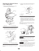
starting the engine raise the grass deflector on the #1 cutting unit (center) and tighten fasteners to retain the deflector in the raised position. Operator Duties 1. Sit on the seat and engage parking brake. 2. Turn reel speed knob counterclockwise to slowest (#1) position. 3. Start the engine and run at minimum throttle. Lower either: Figure 23 • The center 3 cutting units (#1, 2 & 3 ) or • Left-hand (#4) cutting unit or 2.
4. When it becomes necessary to adjust the reel to the bedknife, instruct the operator to disengage the reel, stop the engine and remove the key from the ignition switch. Then proceed with the adjustment only after the reels have stopped rotating. 2 3 5. Backlap each reel until the cutting edges are sharp, even, and consistent on all blades. Achieve a minimum of 1/32 in. (0.79 mm) land area on newly sharpened reel assemblies. Normally, a reel need only be backlapped for approximately 3 minutes. 6.
Installing the Bedknife/Bedbar 1. Thoroughly clean the bedknife mounting face on the bedbar of all rust and scale. Remove any material on the mounting face of the bedbar that will affect a good match-up with the bedknife. 4 2. Before installation, apply a coating of Never Seez, or any material that will ease future disassembly of the bedknife mounting screws to the threads before installation. 3. Use a torque wrench and Part No. 51-0880 special tool to finish tightening the screws (Fig. 27).
4. Disassemble the cone nut from the shoulder bolt securing the bearing housing to the sideplate, remove the Belleville washer and bolt, and slide the bearing housing off of the reel shaft (Fig. 30). 5. Remove the cover from the drive housing and remove the drive belt from the housing (Fig. 30). 5 6 4 1 2 1 7 3 Figure 31 2 1. 2. 3. 4. Figure 30 1. Drive housing (cover removed) Reel capscrew Pulley washer Driven pulley Drive housing 5. Adjusting handle assembly 6. Woodruff key 7.
Installing the Reel Assembly 10. Ensure the slot in the pulley washer is aligned with the roll pin in the pulley and install the washer, toothed washer, and reel capscrew (Fig. 31). Apply a medium strength thread locking compound to the reel capscrew during assembly. Torque the capscrew to 45–55 ft.-lb. 1. Inspect the flange bushings in the mounting holes for the drive housing and bearing housing for wear (Fig. 29). Replace, if necessary. 2.
2 3 1 Figure 34 1. Cone nut 2. Rod and collar assembly 3. Flex locknut 2. The threaded rod and collar assembly can be removed from the roller by sliding it off the shaft at both ends (Fig. 34). Installing the Roller Important When assembling a new roller to the cutting unit, mount the roller so that the roller shaft locknut is on the right side of the cutting unit (Fig. 34) (as viewed by the operator sitting on the seat of the machine). This prevents the locknut from loosening during operation.
The Toro General Commercial Products Warranty A Two-Year Limited Warranty Conditions and Products Covered The Toro Company and its affiliate, Toro Warranty Company, pursuant to an agreement between them, jointly warrant your Toro Commercial Product (“Product”) to be free from defects in materials or workmanship for two years or 1500 operational hours*, whichever occurs first.