
Operator's Manual
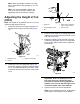

ServicingtheHDDualPoint
Adjusters(DPA)
1.Removeallparts(refertotheInstallation
InstructionsfortheHDDPAKit(ModelNo.
120-7230)andtoFigure37).
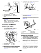
2.Applyanti-seizecompoundtotheinsideofthe
bushingareaonthecarrierframeofthecutting
unit(Figure37).
3.Alignthekeysonangebushingstotheslotsin
theframeandinstallthebushings(Figure37).
4.Installawavewasherontotheadjustershaftand
slidetheadjustershaftintotheangebushings
intheframeofthecuttingunit(Figure37).
5.Securetheadjustershaftwithaatwasherand
locknut(Figure37).T orquethelocknutto20to
27N∙m(15to20ft-lb).
Note:Thebedbaradjustershafthasleft-hand
threads.
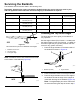
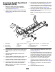
g016926
Figure37
1.Shaftadjuster
4.Applyanti-seizecompound
here.
7.Applyanti-seizecompound
here.
10.Compressionspring
2.Wavewasher5.Flatwasher8.Bedbar-adjusterscrew
11.Spring-tensionnut
3.Flangebushing
6.Locknut9.Hardenedwasher
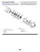
6.Applyanti-seizecompoundtothethreadsofthe
bedbar-adjusterscrewthattintotheadjuster
shaft.
7.Threadthebedbar-adjusterscrewintothe
adjustershaft.
8.Looselyinstallthehardenedwasher,spring,and
spring-tensionnutontotheadjusterscrew.
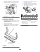
9.Installthebedbar,positioningthemountingears
betweenthewasherandthebedbaradjuster.
10.Securethebedbartoeachsideplatewiththe
bedbarbolts(nutsonbolts)and6washers.
Note:Positionanylonwasheroneachsideof
thesideplateboss.
Placeasteelwasheroutsideeachofthenylon
washers(Figure37).
Torquethebedbarboltsto37to45N∙m(27to33
ft-lb).Tightenthelocknutsuntiltheoutsidesteel
washerstopsrotatingandendplayisremoved,
butdonotovertightenordeectthesideplates.
Thewashersontheinsidemayhaveagap.
11.Tightenthenutoneachbedbar-adjuster
assemblyuntilthecompressionspringisfully
compressed,thenloosenthenut1/2turn(Figure
37).
12.Repeattheprocedureontheotherendofthe
cuttingunit.
13.Adjustthebedknifetothereel.
19