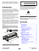
Form No. 3429-864 Rev A 8 and 11-Blade 27-inch and 8-Blade 32-inch EdgeSeries DPA Cutting Unit Reelmaster® 7000-D Traction Unit Model No. 03721—Serial No. 403447001 and Up Model No. 03722—Serial No. 403447001 and Up Model No. 03727—Serial No. 403447001 and Up Register at www.Toro.com.
This product complies with all relevant European directives. For details, please see the Declaration of Incorporation (DOI) at the back of this publication. Model No. Serial No. This manual identifies potential hazards and has safety messages identified by the safety-alert symbol (Figure 2), which signals a hazard that may cause serious injury or death if you do not follow the recommended precautions.
Safety Improperly using or maintaining this machine can result in injury. To reduce the potential for injury, comply with these safety instructions and always pay attention to the safety-alert symbol , which means Caution, Warning, or Danger—personal safety instruction. Failure to comply with these instructions may result in personal injury or death. This machine has been designed in accordance with EN ISO 5395 and ANSI B71.4–2017. General Safety This product is capable of amputating hands and feet.
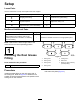
Setup Loose Parts Use the chart below to verify that all parts have been shipped. Procedure 1 2 3 Description Use Qty. Straight grease fitting 1 Install the reel grease fitting. No parts required – Adjust the cutting unit O-ring Cap screws (may come assembled) 1 2 Install the reel motors. Media and Additional Parts Description Qty.
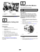
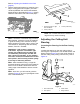
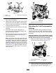
3 Installing the Reel Motors Parts needed for this procedure: g028640 3. Grease fitting 2. Setscrew 4. Grease vent 2. O-ring 2 Cap screws (may come assembled) Procedure Figure 4 1. Cap screw (2) 1 Important: Before installing the reel motors, obtain and install the counter weights or other accessories on the opposite side of the cutting units from the reel motors as described in the instructions provided with the weights or accessories. Install the straight grease fitting (Figure 4).
Product Overview Operation Specifications Note: Determine the left and right sides of the machine from the normal operating position. Model Number Weight 03721 66 kg (145 lb) 03722 68 kg (150 lb) 03727 74 kg (162 lb) Adjusting the Cutting Unit Adjusting the Rear Shield Under most conditions, you can attain the best clipping dispersion when the rear shield is closed (front discharge). When conditions are heavy or wet, you may open the rear shield.
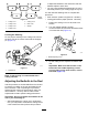
Refer to Adjusting the Bedknife to the Reel (page 8). 2. Test the cutting performance by inserting a long strip of cutting performance paper (Toro Part 125-5610) between the reel and the bedknife, perpendicular to the bedknife (Figure 7). Slowly rotate the reel forward; it should cut the paper. g031270 Figure 8 1. Lead-in chamfer on right end of bedknife 2. 6 mm (0.25 inch) 3. 1.5 mm (0.060 inch) g027166 Figure 7 Note: Do not make the lead-in chamfer too large as it may cause turf tufting.
to adjust the bedknife to the reel as the reel and bedknife adjust to each other. • You may need additional adjustments if the turf is extremely dense or your cutting height is very low. You will need the following tools to complete this procedure: • Shim 0.05 mm (0.002 inch) (Part No. 125-5611) g031275 Figure 10 1. Cutting unit 1 5. Cutting unit 5 2. Cutting unit 2 6. Reel motor 3. Cutting unit 3 7. Weight • Cutting performance paper (Part No. 125-5610) 1.
on both sides prevents the shim from passing through on both sides. Note: The bedknife is now parallel to the reel. Note: This procedure should not be needed on daily adjustments, but should be done after grinding or disassembly. 11. From this position (i.e., 1 click in and shim not passing through) turn the bedbar adjusters clockwise 1 click each. Note: Each click turned moves the bedknife 0.022 mm (0.0009 inch). Do not overtighten the adjusting screws. 12.
g003324 Figure 15 1. Spacer 3. Side-plate mounting flange 2. Roller bracket 2. Raise the rear of the cutting unit and place a block under the bedknife. 3. Remove the 2 nuts securing each roller bracket and spacer to each side-plate mounting flange. 4. Lower the roller and screws from the side-plate mounting flanges and spacers. 5. Place the spacers onto the screws on the roller brackets. 6.
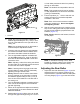
Note: When operating the machine on rough terrain, decrease the spring length by 12.7 mm (1/2 inch). Note: The turf-compensation setting will need to be reset if the HOC setting or the aggressiveness-of-cut setting is changed. Adjusting the Height of Cut (HOC) g003327 Figure 19 Note: For heights of cut greater than 2.54 cm (1 inch) install the High Height-of-Cut Kit. 1. Loosen the locknuts securing the height-of-cut brackets to the cutting-unit side plates (Figure 18). 1. Gauge bar 4.
Height-of-Cut Chart With Groomer kits installed** HOC Setting Aggressiveness of Cut 5+ Y Less 5 5 - 0 5+ Y Normal 6 5 - More 1 5+ - 4.13 cm (1.
Use the following chart to determine which bedknife is best suited for the desired height of cut. Bedknife/Height of Cut Chart Bedknife Part No. Bedknife Lip Height Height of Cut Low HOC (Optional) 120-1641 (27 inch) 5.6 mm (0.220 inch) 6.4 to 12.7 mm (0.250 to 0.500 inch) 6.9 mm (0.270 inch) 9.5 to 63.5 mm (0.375 to 2.50 inches)* 6.9 mm (0.270 inch) 9.5 to 63.5 mm (0.375 to 2.50 inches)* 9.3 mm (0.370 inch) 12.7 to 63.5 mm (0.500 to 2.
the after-cut appearance could be negatively affected (Figure 22). Chain Links The location at which the lift-arm chain is attached determines the pitch angle of the rear roller (Figure 23). g020410 Figure 23 1. Lift chain 2. U bracket 3. Bottom hole Groomer These are the recommended height-of-cut settings when a groomer kit is installed on the cutting unit.
Maintenance The lubrication points are the front roller (2), the rear roller (2), and at the reel motor spline (1). Using the Kickstand When Tipping the Cutting Unit Note: Lubricating the cutting units immediately after washing helps purge water out of the bearings and increases bearing life.
Servicing the Bedknife The bedknife service limits are listed in the following chart. Important: Operating the cutting unit with the bedknife below the service limit may result in poor after-cut appearance and reduce the structural integrity of the bedknife for impacts. Bedknife Service Limit Chart Bedknife Part No. Bedknife Lip Height Service Limit* Grind Angles Top/Front Angles Low HOC (Optional) 120-1641 (27 inch) 120-1642 (32 inch) 5.6 mm (0.220 inch) 4.8 mm (0.
3. On each side of the machine, loosen the locknut securing the bedbar bolt (Figure 32). g003334 Figure 32 1. Bedbar bolt 2. Lock nut g034114 Figure 30 1. Angle-indicator mount 4. 3. Bedknife 2. Edge of the magnet mated 4. Angle indicator with the edge of the bedknife 4. Remove each bedbar bolt, allowing the bedbar to be pulled downward and removed from machine bolt (Figure 32). Note: Account for 2 nylon washers and 1 stamped steel washer on each end of the bedbar (Figure 33).
4. Tighten the spring-tension nut until the spring is collapsed, then back off 1/2 turn (Figure 34). A. Torque the 2 outer screws to 1 N∙m (10 in-lb); refer to Figure 35. B. Working form the center of the bedknife, torque the screws to 23 to 28 N∙m (200 to 250 in-lb); refer to Figure 35. g016648 Figure 34 1. Spring-tension nut 2. Spring Installing the Bedknife 1. g279162 Figure 36 Remove the rust, scale, and corrosion from the bedbar surface and apply a thin layer of oil to the bedbar surface.
Servicing the HD Dual Point Adjusters (DPA) 1. 2. Remove all parts (refer to the Installation Instructions for the HD DPA Kit (Model No. 120-7230) and to Figure 37). 3. Align the keys on flange bushings to the slots in the frame and install the bushings (Figure 37). 4. Install a wave washer onto the adjuster shaft and slide the adjuster shaft into the flange bushings in the frame of the cutting unit (Figure 37). 5. Secure the adjuster shaft with a flat washer and locknut (Figure 37).
Servicing the Roller nuts, inner seals, and outer seals to rebuild a roller. The Roller Rebuild Tool Kit includes all the tools and the installation instructions required to rebuild a roller with the Roller Rebuild Kit. Refer to your Parts Catalog or contact your distributor for assistance. The Roller Rebuild Kit and the Roller Rebuild Tool Kit (Figure 38) are available for servicing the roller. The Roller Rebuild Kit includes all the bearings, bearing g007790 Figure 38 1. Rebuild kit (Part No.
Notes:
Declaration of Incorporation The Toro Company, 8111 Lyndale Ave. South, Bloomington, MN, USA declares that the following unit(s) conform(s) to the directives listed, when installed in accordance with the accompanying instructions onto certain Toro models as indicated on the relevant Declarations of Conformity. Model No. Serial No.
EEA/UK Privacy Notice Toro’s Use of Your Personal Information The Toro Company (“Toro”) respects your privacy. When you purchase our products, we may collect certain personal information about you, either directly from you or through your local Toro company or dealer.
The Toro Warranty Two-Year or 1,500 Hours Limited Warranty Conditions and Products Covered Parts The Toro Company and its affiliate, Toro Warranty Company, pursuant to an agreement between them, jointly warrant your Toro Commercial product (“Product”) to be free from defects in materials or workmanship for 2 years or 1,500 operational hours*, whichever occurs first. This warranty is applicable to all products with the exception of Aerators (refer to separate warranty statements for these products).