Form No. 3407-884 Rev A 27-inch Verticutter Reelmaster® 7000-D Cutting Unit Model No. 03731—Serial No. 400000000 and Up Register at www.Toro.com.
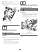
WARNING Model No. CALIFORNIA Proposition 65 Warning This product contains a chemical or chemicals known to the State of California to cause cancer, birth defects, or reproductive harm. Serial No. This manual identifies potential hazards and has safety messages identified by the safety alert symbol (Figure 2), which signals a hazard that may cause serious injury or death if you do not follow the recommended precautions. This product complies with all relevant European directives.
Safety • Remove all debris or other objects that might be picked This machine has been designed in accordance with EN ISO 5395:2013. • If the verticutter blades strike a solid object or the unit up and thrown by the reel blades of the cutting unit. Keep all bystanders away from the working area. vibrates abnormally, stop and shut off the engine. Check the verticutter for damaged parts. Repair any damage before starting and operating the verticutter.
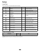
Setup Loose Parts Use the chart below to verify that all parts have been shipped. Procedure Description 1 2 3 4 5 6 7 8 9 10 11 Use Qty. Verticutter 1 Inspect the verticutter. Transport roller assembly Cotter pin O-ring Grease fitting Turf-compensation assembly Long bolt Carriage bolt Flange locknut Flange nut 2 2 1 1 1 1 2 3 1 No parts required – Adjust the blade depth. No parts required – Adjust the rear grass shield. No parts required – Adjust the roller scrapers.
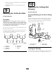
Note: Determine the left and right sides of the machine from the normal operating position. 2 Note: Whenever the verticutter has to be tipped to expose the verticutter blades, use the kick stand (supplied with traction unit) (Figure 3). Installing the Transport Rollers Parts needed for this procedure: 2 Transport roller assembly 2 Cotter pin Procedure 1.
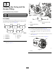
1 3 Installing the O-ring and the Grease Fitting Parts needed for this procedure: 1 O-ring 1 Grease fitting G028407 Procedure 3 2 g028407 The grease fitting must be installed on the reel motor side of the verticutter. Use the following diagram to determine the position of each reel motor (Figure 5). Figure 6 1. Bolts 3. Setscrew (remove and discard) 2. Straight grease fitting (install) 2. Install the straight grease fitting (Figure 6). 3.
4 5 Installing the Turf-Compensation Spring Adjusting the Blade Depth No Parts Required Parts needed for this procedure: 1 Turf-compensation assembly 1 Long bolt 2 Carriage bolt 3 Flange locknut 1 Flange nut Procedure Note: The maximum recommended blade penetration depth is 6 mm (1/4 inch). 1. Place the verticutter reel on a level surface. 2.
6 7 Adjusting the Rear Grass Shield Adjusting the Roller Scrapers No Parts Required No Parts Required Procedure 1. Loosen the flange nuts that secure the roller scrapers (Figure 11). Procedure Note: When operating in turf conditions where much debris or unusually heavy thatch is encountered, open the rear discharge shield to help allow the debris to discharge from the reel. 1. Loosen the bolts on the pivot of the grass shield (Figure 10). g195551 Figure 11 1. Flange nuts 3. Rear roller scraper 2.
3. Secure the transport roller bracket to the side plate pin with the cotter pin. 10 4. Repeat the procedure on the opposite end of the verticutter.
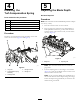
1 G015977 g015977 Figure 14 1. Snapper pin g196971 Note: Fixed steering is recommended when cutting side hills. Figure 15 11 1. Hairpin cotter 3. Turf-compensation spring 2. Spring rod 4. Hex nuts 2. Tighten the hex nuts on the front end of the spring rod until the compressed length of the spring is 15.9 cm (6.25 inches) (Figure 15). Adjusting the Turf-Compensation Settings Note: When operating the machine on rough terrain, decrease the spring length by 12.7 mm (1/2 inch).
Product Overview Operation Specifications Note: Determine the left and right sides of the machine from the normal operating position. Net weight 64 kg (140 lb) Training Period Before operating the verticutter reels, evaluate the performance of the reel at the desired setting. Operate in a clear, unused area to determine whether the desired results will be achieved. Make adjustments as necessary. Operating Tips 1.
Maintenance with a light coating of grease to simplify the assembly (Figure 17). Lubricating the Verticutter Each verticutter has 5 grease fittings (Figure 16) that must be lubricated weekly with No. 2 lithium grease. The lubrication points are the front roller (2), the rear roller (2), and the reel motor splines (1). Important: Lubricating the cutting units immediately after washing helps purge water out of the bearings and increases bearing life. 1. Wipe each grease fitting with a clean rag. 2.
Installing the Verticutter Blades 1. Assemble a reel blade (Figure 18). 2. Assemble a large spacer. 3. Do not invert the reel blades when reassembling them onto the reel shaft. Note: If the blades are inverted, the blades that are in use (rounded) will be mixed with the sharp ends of the blades which were not in use. This will cause unsatisfactory performance in the verticutter reel unit. Pay close attention when disassembling the verticutter blades from the reel. 4.
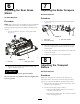
g007790 Figure 19 1. Rebuild kit (Part No. 114–5430) 6. Bearing nut 2. Rebuild tool kit (Part No. 115–0803) 7. Inner seal tool 3. Inner seal 4. Bearing 8. Washer 9. Bearing/outer seal tool 5.
Notes:
Notes:
Notes:
Declaration of Incorporation The Toro Company, 8111 Lyndale Ave. South, Bloomington, MN, USA declares that the following unit(s) conform(s) to the directives listed, when installed in accordance with the accompanying instructions onto certain Toro models as indicated on the relevant Declarations of Conformity. Model No. 03731 Serial No.
European Privacy Notice The Information Toro Collects Toro Warranty Company (Toro) respects your privacy. In order to process your warranty claim and contact you in the event of a product recall, we ask you to share certain personal information with us, either directly or through your local Toro company or dealer. The Toro warranty system is hosted on servers located within the United States where privacy law may not provide the same protection as applies in your country.
The Toro Warranty A Two-Year Limited Warranty Conditions and Products Covered The Toro Company and its affiliate, Toro Warranty Company, pursuant to an agreement between them, jointly warrant your Toro Commercial product (“Product”) to be free from defects in materials or workmanship for two years or 1500 operational hours*, whichever occurs first. This warranty is applicable to all products with the exception of Aerators (refer to separate warranty statements for these products).