Form No. 3443-652 Rev A 27-inch Verticutter Reelmaster® 7000-D Cutting Unit Model No. 03731—Serial No. 407900000 and Up Register at www.Toro.com.
This product complies with all relevant European directives. For details, please see the Declaration of Incorporation (DOI) at the back of this publication. Model No. Serial No. This manual identifies potential hazards and has safety messages identified by the safety-alert symbol (Figure 2), which signals a hazard that may cause serious injury or death if you do not follow the recommended precautions.
Safety instruction. Failure to comply with these instructions may result in personal injury or death. This machine has been designed in accordance with EN ISO 5395 and ANSI B71.4–2017. Cutting Unit Safety • The cutting unit is only a complete machine when General Safety installed on a traction unit. Read the traction unit Operator’s Manual carefully for complete instructions on the safe use of the machine. This product is capable of amputating hands and feet.
Safety and Instructional Decals Safety decals and instructions are easily visible to the operator and are located near any area of potential danger. Replace any decal that is damaged or missing. decal137-9706 137-9706 1. Cutting hazard of the hand or foot—shut off the engine, remove the key or disconnect the spark plug, wait for all moving parts to stop, and read the Operator’s Manual before performing maintenance.
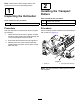
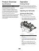
Setup Loose Parts Use the chart below to verify that all parts have been shipped. Procedure 1 2 3 4 5 6 Description Use Qty. Verticutter 1 Inspect the verticutter. Transport roller assembly Cotter pin O-ring Grease fitting Turf-compensation assembly Long bolt Carriage bolt Flange locknut Flange nut 2 2 1 1 1 1 2 3 1 No parts required – Adjust the verticutter. No parts required – Mount the verticutter reel. Install the transport rollers. Install the O-ring and the grease fitting.
Note: Determine the left and right sides of the machine from the normal operating position. 2 1 Installing the Transport Rollers Inspecting the Verticutter Parts needed for this procedure: Parts needed for this procedure: 1 Verticutter 2 Transport roller assembly 2 Cotter pin Procedure Procedure After the verticutter is removed from the box, inspect the following: Secure a transport roller bracket to each side plate pin with a cotter pin (Figure 3). 1. Check each end of the reel for grease.
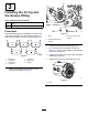
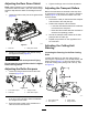
3 Installing the O-ring and the Grease Fitting Parts needed for this procedure: 1 O-ring 1 Grease fitting Procedure g028407 Figure 5 The grease fitting must be installed on the reel motor side of the verticutter. Use the following diagram to determine the position of each reel motor (Figure 4). 1. Bolts 3. Setscrew (remove and discard) 2. Straight grease fitting (install) g031275 2. Install the straight grease fitting (Figure 5). 3.
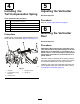
4 5 Installing the Turf-Compensation Spring Adjusting the Verticutter No Parts Required Parts needed for this procedure: 1 Turf-compensation assembly 1 Long bolt 2 Carriage bolt 3 Flange locknut 1 Flange nut Procedure Refer to Adjusting the Verticutter (page 9). 6 Mounting the Verticutter Reel Procedure Install the turf compensation spring assembly on the same side as the reel motor (Figure 4 and Figure 7).
Product Overview Operation Specifications Training Period Net weight Before operating the verticutter reels, evaluate the performance of the reel at the desired setting. Operate in a clear, unused area to determine whether the desired results will be achieved. Make adjustments as necessary. 64 kg (140 lb) Attachments/Accessories A selection of Toro approved attachments and accessories is available for use with the machine to enhance and expand its capabilities.
Adjusting the Rear Grass Shield 4. Note: When operating in turf conditions where there is excessive debris or thatch, open the rear discharge shield to help allow the debris to discharge from the reel. 1. Tighten the flange nuts to lock the adjustment. Adjusting the Transport Rollers Before the verticutters are lowered to the shop floor or removed from the traction unit, lower the transport rollers (Figure 10) to protect the blades from hard surface contact.
g031275 Figure 12 1. Cutting unit 1 5. Cutting unit 5 2. Cutting unit 2 6. Reel motor 3. Cutting unit 3 7. Weight 4. Cutting unit 4 Locking the Steering g196971 Figure 14 To lock (fix) the steering on the cutting units, secure the pivot yoke to the carrier frame with the snapper pin (Figure 13). 1. Hairpin cotter 3. Turf-compensation spring 2. Spring rod 4. Hex nuts 2. Tighten the hex nuts on the front end of the spring rod until the compressed length of the spring is 15.9 cm (6.
Maintenance Lubricating the Verticutter Each verticutter has 5 grease fittings (Figure 16) that must be lubricated weekly with No. 2 lithium grease. Using the Kickstand When Tipping the Cutting Unit The lubrication points are the front roller (2), the rear roller (2), and the reel motor splines (1). Note: Whenever the verticutter has to be tipped to expose the verticutter blades, use the kickstand (supplied with traction unit) (Figure 15).
Installing the Verticutter Blades Removing the Verticutter Blades from the Shaft 1. Secure the end of the verticutter shaft, which has only one washer and nut, in a vise. 2. On other end of shaft, rotate the nut counter-clockwise and remove the nut. 1. Assemble a reel blade (Figure 18). 2. Assemble a large spacer. 3. Do not invert the reel blades when assembling them onto the reel shaft.
Optional Blade Spacing Changing the configuration of the verticutter from the standard 1.20-inch spacing to the optional 0.94-inch spacing requires an additional 23 spacers (Part No. 140-5532) and an additional 5 carbide-tip blades (Part No. 106-8625) as shown in Figure 19. g349402 Figure 19 2. 0.94-inch blade spacing 1. 1.
Servicing the Roller inner seals, and outer seals to rebuild a roller. The Roller Rebuild Tool Kit includes all the tools and the installation instructions required to rebuild a roller with the roller rebuild kit. Refer to your parts catalog or contact your authorized Toro distributor for assistance. The Roller Rebuild Kit (Part No. 114-5430) and the Roller Rebuild Tool Kit (Part No. 115-0803) (Figure 20) are available for servicing the roller.
Notes:
Notes:
Declaration of Incorporation The Toro Company, 8111 Lyndale Ave. South, Bloomington, MN, USA declares that the following unit(s) conform(s) to the directives listed, when installed in accordance with the accompanying instructions onto certain Toro models as indicated on the relevant Declarations of Conformity. Model No. 03731 Serial No.
EEA/UK Privacy Notice Toro’s Use of Your Personal Information The Toro Company (“Toro”) respects your privacy. When you purchase our products, we may collect certain personal information about you, either directly from you or through your local Toro company or dealer.
The Toro Warranty Two-Year or 1,500 Hours Limited Warranty Parts Conditions and Products Covered The Toro Company warrants your Toro Commercial product (“Product”) to be free from defects in materials or workmanship for 2 years or 1,500 operational hours*, whichever occurs first. This warranty is applicable to all products with the exception of Aerators (refer to separate warranty statements for these products).