
Operator's Manual


AdjustingtheRearGrassShield
Note:Whenoperatinginturfconditionswherethere
isexcessivedebrisorthatch,openthereardischarge
shieldtohelpallowthedebristodischargefromthe
reel.
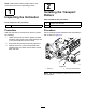
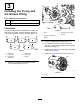
1.Loosentheboltsonthepivotofthegrassshield
(Figure9).
g195550
Figure9
1.Pivotbolt2.Reargrassshield
2.Rotatethegrassshieldtothedesiredsetting,
andtightenthebolts(Figure9).
CAUTION
Throwndebriscouldcausepersonalinjury.
Donotopentherearshieldsothatitishigher
thanleveltoground.
AdjustingtheRollerScrapers
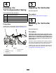
1.Loosentheangenutsthatsecuretheroller
scrapers(Figure10).
g313796
Figure10
1.Frontrollerscraper3.Transportroller
2.Cotterpin
4.Rearrollerscraper
2.Movethescraperrodsinorouttoattain0.0to
0.75mm(0.0to0.03inch)clearancebetween
thescraperandtheroller.
3.Ensurethatthescraperrodisparalleltothe
rollerandtothelevelsurface.
4.Tightentheangenutstolocktheadjustment.
AdjustingtheTransportRollers
Beforetheverticuttersareloweredtotheshopoor
orremovedfromthetractionunit,lowerthetransport
rollers(Figure10)toprotectthebladesfromhard
surfacecontact.
1.Removethecotterpinthatsecuresthetransport
rollerbrackettothesideplatepin.
2.Positionthetransportrollerasfollows:
•Lowertherollerbracketbeforetheverticutter
isloweredtotheshopoor.
•Raisetherollerbracketaftertheverticutteris
raisedtotheoperatingposition.
3.Securethetransportrollerbrackettotheside
platepinwiththecotterpin.
4.Repeattheprocedureontheoppositeendof
theverticutter.
AdjustingtheCutting-Unit
Steering
IncreasingtheSteeringfortheRearCutting
Units
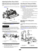
Increasethesteeringontherearcuttingunitsby
removingthe2pivotspacers,hexsocketscrews,and
angelocknuts(Figure11)fromthecarrierframes
oftherearcuttingunits(cuttingunits2and3);refer
toFigure12.
g015978
Figure11
1.Hexsocketscrew
3.Carrierframe
2.Pivotspacer4.Flangelocknut
10