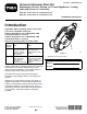
Form No. 3443-389 Rev A Universal Groomer Drive Kit Reelmaster® 18-inch, 22-inch, or 27-inch EdgeSeries™ Cutting Units with 5-inch or 7-inch Reel Model No. 03763—Serial No. 321000000 and Up Model No. 03768—Serial No. 321000000 and Up Installation Instructions Introduction Important: Before installing this kit, ensure that you have a compatible cutting unit: 03763 is designed for use on Reelmaster DPA Cutting Units with a 5 inch reel.
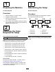
Loose Parts Use the chart below to verify that all parts have been shipped. Procedure 1 2 3 Description Qty. Use No parts required – Prepare the machine. Torque wrench (Not included) – Gather the tools required for setup. No parts required – Determine where on the cutting unit to install the groomer.
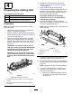
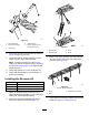
1 3 Preparing the Machine Determining the Setup No Parts Required No Parts Required Procedure Procedure 1. Park the machine on a level surface. 2. Engage the parking brake. 3. Shut off the engine and remove the key; refer to your Operator’s Manual. 4. If the cutting unit is installed, remove the cutting unit from the traction unit; refer to the Operator’s Manual for the traction unit. Use the following diagram to determine the position of the groomer kit and reel motors.
4. Restrain the reel to install the new insert; Restraining the Reel for Installing Threaded Inserts (page 20). 5. Apply medium-strength thread-locking compound (such as Blue Loctite® 243) to the threads of the new longer splined insert, and secure it to the reel shaft. Torque the insert to 115 to 128 N∙m (85 to 95 ft-lb).
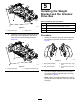
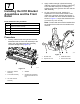
Installing the Weight Bracket and the Groomer Drive Box Parts needed for this procedure: g037064 5 Weight bracket 10 Hex-socket, button-head bolt (3/8 x 3/4 inch) 3 Groomer drive box (left drive) 2 Groomer drive box (right drive) Figure 5 1. Flange-head bolts B. 2. Support rod Install the 2 existing flange-head bolts from the inside of the cutting unit, and secure them with the 3/8-inch flange locknuts (Figure 6). Procedure 1.
Installing the Idler Assembly Parts needed for this procedure: 10 Hex-socket bolt 5 Pivot hub 5 O-ring 2 Idler assembly (left) 3 Idler assembly (right) 10 Flange locknut (3/8 inch)—Model 03763 only 10 Jam locknut (3/8 inch)—Model 03768 only g346923 Figure 8 1. Weight bracket 4. Thread-locking compound 2. Hex-socket, button-head bolt—3/8 x 3/4 inch (2) 5. Hex-head (Torque to 135 to 150 N∙m (100 to 110 ft-lb)) Procedure 3. Groomer drive box (left drive shown) 3. 4.
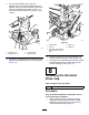
Installing the HOC Bracket Assemblies and the Front Roller Parts needed for this procedure: 5 Left HOC bracket assembly 5 Right HOC bracket assembly 10 Shoulder bolt 5 Hardened washer 10 Flange locknut (3/8 with 5/8 hex) 2. Apply medium-strength cylindrical bonding retaining compound (such as Blue Loctite 242®) to the shoulder bolts prior to installing the adjuster arms to the groomer drive box and the idler assembly. 3.
4. On the idler assembly side, align the adjuster-arm rod of the HOC bracket with the adjuster collar on the idler assembly and secure it with a shoulder bolt as shown in Figure 12; torque the shoulder bolt to 20 to 26 N⋅m (15 to 19 ft-lb). g346926 Figure 13 g346925 3. Adjuster collar 2. Adjuster-arm rod 4. Idler assembly 5. 4. Flange nut 2. Locknut 5. Capscrew 3. Carriage bolt and flange locknut (3/8 with 5/8 inch hex) Figure 12 1. Shoulder bolt 1.
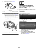
2. Install the cap as shown in Figure 14. 9 Installing the Groomer Assembly and Optional Broomer Kit Groomer and Broomer Kits Come Separately g346927 Figure 14 1. Cap 3. 2. Apply Green Loctite 609® Parts needed for this procedure: If you are installing the groomer at the left side of the machine, perform the following (Figure 15): 20 Bolt (1/4 x 1-1/2 inches) A. Remove the hex-socket screw that secures the clutch knob to the actuator shaft. 20 Jam nut 20 Shaft clamp B.
g240752 Figure 16 1. Drive-stub shaft 4. Shaft clamp (4) 2. Groomer assembly 5. Bolt (4) Torque to 5 to 7 N∙m (46 to 60 in-lb) g032403 Figure 17 3. Jam nut (4) 3. Secure the groomer to the machine as shown in Figure 16 and snug the bolts. 4. To prevent binding, set the height of cut and height of groom, then loosen the bolts. 1. Strap buckle 3. Strap 2. Retaining nut 4. Brush 3.
10 Adjusting the Groomer Spring Force Parts needed for this procedure: g032402 – Figure 19 1. Brush Washer (Part No. 3256-24, not included) 2. Blade Procedure 5. Loosely wrap the straps, as shown in Figure 17, around the groomer reel shaft and brushes inserting the straps in the grooves in the brushes Figure 19. For low height-of-groom setups where additional spring force is required, install additional washers (Part No.
5. Subtract the desired (.75 inch or 19 mm) spring length from the current spring length, and divide this difference by 0.06 inches to determine how many washers you need to add to achieve the desired spring length. 11 Installing the Angled Fitting For Reelmaster 3550 and 3555 Machines—#1 Front, Center Cutting Location and Kit Model 133-0150 Only Parts needed for this procedure: 1 Hydraulic fitting—45° (Part No.
Operation • The type of grass • The overall management program (i.e., irrigation, fertilizing, spraying, coring, overseeding, etc.) Introduction • Traffic Grooming is performed in the turf canopy above the soil level. Grooming promotes vertical growth of grass plants, reduces grain, and severs stolons, producing a denser turf. Grooming produces a more uniform and tighter playing surface for faster and truer action of the golf ball. • Stress periods (i.e.
Adjusting the Groomer Height 1. Park the machine on a clean and level surface, lower the cutting units completely to the ground, shut off the engine, engage the parking brake, and remove the key. 2. Make sure that the rollers are clean and the cutting unit is set to the desired height-of-cut (see your cutting unit Operator’s Manual). 3. Rotate the quick-up levers (Figure 23) to the ENGAGED position (the handle points toward the front of the cutting unit.
Height-of-Cut (HOC) and Height-of-Groom (HOG) Recommended Range Height-of-Cut (mm) Height-of-Cut (inch) Number of Rear Roller Spacers Recommended HOG = HOC Groomer Engagement Recommended HOG = HOC Groomer Engagement (mm) (inch) 6.3 0.250 0 3.1 to 6.3 0.125 to 0.250 9.5 0.375 0 4.7 to 9.5 0.187 to 0.375 9.5 0.375 1 4.7 to 9.5 0.187 to 0.375 12.7 0.500 0 6.3 to 12.7 0.250 to 0.500 12.7 0.500 1 6.3 to 12.7 0.250 to 0.500 12.7 0.500 2 6.3 to 9.5 0.250 to 0.375 15.8 0.
Transporting the Machine Testing the Groomer Performance When you wish to mow without the groomer or need to transport the machine, move the quick-up lever to the TRANSPORT position (Figure 25). Important: Improper or over-aggressive use of the grooming reel (i.e., too deep or too frequent grooming) may cause unnecessary stress on the turf, leading to severe damage. Use the groomer cautiously. Note: This moves the groomer reel into a raised position.
Maintenance 8. Use the included syringe (Part No. 137-0872) to fill the drive box with 80-90W oil. Fill with 50 cc for 5-inch reels or 90 cc for 7-inch reels. Changing the Gearbox Lubricant Service Interval After the first 100 hours Every 500 hours / Yearly (Whichever comes first) 1. Clean the external surfaces of the groomer housing. Important: Ensure that there is no dirt or clippings on the outside of the groomer housing; if debris gets inside of the groomer it can damage the gearbox. 2.
Removing the Groomer Drive Box turn the groomer drive hex-head clockwise (left-hand thread) to remove drive-box shaft from cutting unit Note: Retain all removed parts for later installation unless otherwise stated. Important: You must use a 6-point socket with heavy wall. Important: If you have any issues removing the groomer drive box, refer to your traction unit Service Manual or contact your authorized Toro distributor. 1. Remove the cap from the groomer. 2.
Restraining the Reel WARNING The cutting reel blades are sharp and capable of amputating hands and feet. • Keep your hands and feet outside of the reel. • Ensure that the reel is restrained before servicing it. Restraining the Reel for Removing Threaded Inserts 1. 2. 3. Loosen the shield-bolt on the left side of the cutting unit and raise the rear shield (Figure 31).
Restraining the Reel for Installing Threaded Inserts 1. Insert a long-handled pry bar (recommended 3/8 x 12 inches with a screwdriver handle) through the front of the cutting reel, closest to the side of the cutting unit that you will be torquing (Figure 32). 2. Place the pry bar against the weld side of the internal cutting reel reinforcement (Figure 32). Note: The pry bar should contact a blade at the front, the reel shaft, and a blade at the back of the back of the reel, locking it in place.
Notes:
Declaration of Incorporation The Toro Company, 8111 Lyndale Ave. South, Bloomington, MN, USA declares that the following unit(s) conform(s) to the directives listed, when installed in accordance with the accompanying instructions onto certain Toro models as indicated on the relevant Declarations of Conformity. Model No. Serial No.
EEA/UK Privacy Notice Toro’s Use of Your Personal Information The Toro Company (“Toro”) respects your privacy. When you purchase our products, we may collect certain personal information about you, either directly from you or through your local Toro company or dealer.
The Toro Warranty Two-Year or 1,500 Hours Limited Warranty Parts Conditions and Products Covered The Toro Company warrants your Toro Commercial product (“Product”) to be free from defects in materials or workmanship for 2 years or 1,500 operational hours*, whichever occurs first. This warranty is applicable to all products with the exception of Aerators (refer to separate warranty statements for these products).