
Installation Instructions

g240752
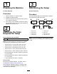
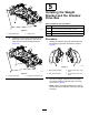
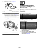
Figure16
1.Drive-stubshaft4.Shaftclamp(4)
2.Groomerassembly5.Bolt(4)Torqueto5to7
N∙m(46to60in-lb)
3.Jamnut(4)
3.Securethegroomertothemachineasshownin
Figure16andsnugthebolts.
4.Topreventbinding,settheheightofcutand
heightofgroom,thenloosenthebolts.
Note:T osettheheightofcutrefertoyour
cuttingunitOperator’sManual;refertoAdjusting
theGroomerHeight(page14)foradjustingthe
heightofgroom.
5.Torquetheboltsto5to7N∙m(46to60in-lb).
6.Checkandadjustheightofcutandheightof
groomasnecessary.
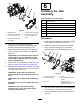
InstallingtheBroomerKit
PartNumberBroomerKit
132-711518-inchBroomerKit
132-712522-inchBroomerKit
133-822227-inchBroomerKit
1.Obtainanoptionalbroomerkitforgroomer
bladecartridgesappropriateforyourneedsand
cuttingunit;refertothetableabove.
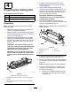
2.Loosenthegroomerblade-retainingnutson
eachendofthegroomershaft(Figure17).
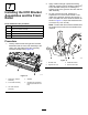
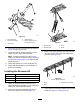
g032403
Figure17
1.Strapbuckle3.Strap
2.Retainingnut4.Brush
3.From1sideofthegroomerreel,slideabrush
intoeachgroovearoundthefulllengthofthe
groomerreel(Figure18).
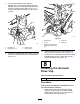
g227786
Figure18
22inchgroomershown
1.Strap3.Towardrearofmachine
2.Brush
4.Verifythatthebrushesareseatedinthegroomer
bladeslots(Figure17andFigure19).
10