
Installation Instructions

g346923
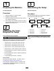
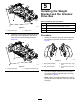
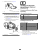
Figure8
1.Weightbracket4.Thread-lockingcompound
2.Hex-socket,button-head
bolt—3/8x3/4inch(2)
5.Hex-head(Torqueto135
to150N∙m(100to110
ft-lb))
3.Groomerdrivebox(left
driveshown)
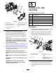
3.Applymedium-strengththread-locking
compound(suchasBlueLoctite®243)tothe
threadsoftheinternalreelshaft(Figure8).
4.Attachthegroomerdriveboxtothereelshaft
(Figure8)usingthehex-headonthegroomer
drivebox.
Important:Thereelthreadsontheleftside
ofthecuttingunitareleft-handed,andthe
reelthreadsontherightsideofthecutting
unitareright-handed.
5.Restrainthecuttingreel;refertoRestrainingthe
ReelforInstallingThreadedInserts(page20).
6.Whilethereelisrestrained,torquethehex-head
ofthedrive-boxshaftto135to150N∙m(100to
110ft-lb);refertoFigure12.
Important:Torquethehexheadofthe
drive-boxshaftto135to150N∙m(100to110
ft-lb).
Important:Usea6-pointsocketwithheavy
wall.
Important:Donotuseanimpactwrenchfor
thisstep.
Important:Allowthethread-locking
compoundtocurefor15minutesbefore
continuingtheprocedure.
6
InstallingtheIdler
Assembly
Partsneededforthisprocedure:
10Hex-socketbolt
5
Pivothub
5
O-ring
2
Idlerassembly(left)
3
Idlerassembly(right)
10
Flangelocknut(3/8inch)—Model03763only
10
Jamlocknut(3/8inch)—Model03768only
Procedure
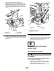
1.Positiontheidlerassemblyontheoppositeside
ofthereelfromthegroomerdrivebox.
2.InstalltheO-ringontothepivot-hubassembly.
3.Applyanti-seizecompoundontheoutside
diameterofthepivot-hubassembly(Figure9).
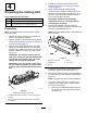
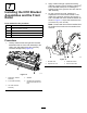
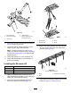
g037106
Figure9
1.Locknut—3/8inch(2)4.O-ring
2.Hex-socketbolt(2)5.Idlerassembly(rightside
shown)
3.Pivothub6.Applyanti-seize
compoundontheoutside
diameterofthehub.
4.Securethepivothubovertheidlerassemblyto
thereelusing2hex-socketbolts(Figure9).
5.Looselyinstallthe2locknutsonthepivothub
(Figure9).
6