
Installation Instructions
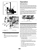
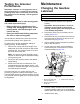


8.Usetheincludedsyringe(PartNo.137-0872)to
llthedriveboxwith80-90Woil.Fillwith50cc
for5-inchreelsor90ccfor7-inchreels.
g240898
Figure26
1.Syringewith80-90Woil
2.Fillport
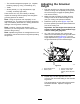
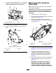
9.Installthellplugandtightentheair-ventplug.
10.Torqueallplugsto3.62to4.75N∙m(32to42
in-lb).
g241100
Figure27
Rightsidegroomerboxshown
1.Air-ventplug3.Drainplug
2.Fillplug
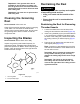
RemovingtheGroomer
DriveBox
Note:Retainallremovedpartsforlaterinstallation
unlessotherwisestated.
Important:Ifyouhaveanyissuesremovingthe
groomerdrivebox,refertoyourtractionunit
ServiceManualorcontactyourauthorizedToro
distributor.
1.Removethecapfromthegroomer.
2.Removetheclampboltsconnectingthegroomer
tothedrivebox(Figure17).
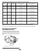
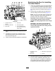
3.Removetheadjusterpinandcotterpin
connectingthegroomerdriveboxtotheadjuster
arms(Figure28).
g307047
Figure28
1.Adjusterpin
3.Groomerdrivehex-head
2.Cotterpin4.Reinforcementscrew
4.Restrainthereelforremoval;refertoRestraining
theReelforRemovingThreadedInserts(page
17).
5.Installthereinforcementscrew(PartNo.
1-803022—soldseparately)totheinternal
threadsofthegroomerdrivehexheadand
torqueto13.5N⋅m(120in-lb)asshownin
Figure28.
6.Removethegroomerdriveboxfromthecutting
reelbyturningthegroomerdrivehex-head
(Figure28).
Important:Ifthegroomerdriveboxis
installedontherightsideofacutting
unit,turnthegroomerdrivehex-head
counter-clockwise(right-handthread)to
removethedrive-boxshaftfromcuttingunit.
16