
Installation Instructions
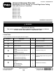
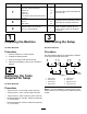
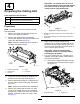
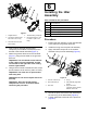
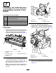
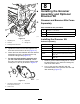
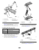

Table Of Contents
- .
- 1 Preparing the Machine
- 2 Gathering the Tools Required for Setup
- 3 Determining the Setup
- 4 Preparing the Cutting Unit
- 5 Installing the Weight Bracket and the Groomer Drive Box
- 6 Installing the Idler Assembly
- 7 Installing the HOC Bracket Assemblies and the Front Roller
- 8 Installing the Groomer Assembly and Optional Broomer Kit
- 9 Installing the Angled Fitting
- NO TITLE
- NO TITLE
ProcedureDescription
Qty.
Use
LeftHOCbracketassembly
5
RightHOCbracketassembly
5
Adjusterpin10
Cotterpin
10
Outercover
5
7
Hex-socket,button-headscrew(5/16x
1/2inch)
5
InstalltheHOCbracketassembliesand
thefrontroller.
Bolt(1/4x1-1/2inches)
20
Jamnut20
8
Shaftclamp
20
Installthegroomerassembly(ordered
separately)andoptionalbroomerkit.
9
Hydraulictting—45°(PartNo.
340–101;soldseparately)
1
Installtheangledtting(forReelmaster
3550and3555machines,#1front,
centercuttinglocationandkitModel
133-0150).
1
PreparingtheMachine
NoPartsRequired
Procedure
1.Parkthemachineonalevelsurface.
2.Engagetheparkingbrake.
3.Shutofftheengineandremovethekey.
4.Disconnectthebattery;refertoyourOperator’s
Manual.
2
GatheringtheTools
RequiredforSetup
NoPartsRequired
Procedure
•T orquewrench—5.2to6.8N∙m(46to60in-lb)
•T orquewrench—115to129N∙m(85to95ft-lb)
•T orquewrench—135to150N∙m(100to110ft-lb)
•Reeldriveshafttool,PartNo.TOR4112(usedonly
on5-inchreels)
•Reeldriveshafttool,PartNo.TOR4074(usedonly
on7-inchreels)
3
DeterminingtheSetup
NoPartsRequired
Procedure
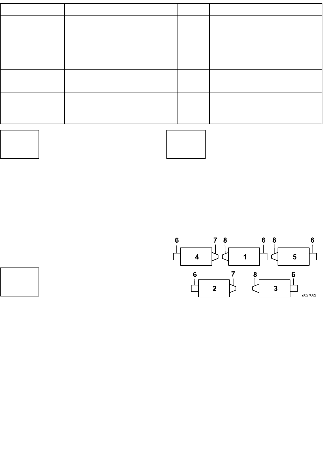
Usethefollowingdiagramtodeterminetheposition
ofthegroomerkitandreelmotors.
g027662
Figure1
1.Cuttingunit15.Cuttingunit5
2.Cuttingunit2
6.Reelmotor
3.Cuttingunit3
7.Rightgroomerkit
4.Cuttingunit48.Leftgroomerkit
Note:Ifyouareinstallingagroomerkitandarear
roller-brushkitonthecuttingunit,installthegroomer
kitrst.
2