
Operator's Manual


FORM NO. 3316-962
The TORO Company - 1996
TPS
INSTALLATION
INSTRUCTIONS
REELMASTER
4500D
MODEL NO. 03776-60001 & UP
LIGHT KIT
Note: Light kit to be used on traction unit models
03702, 03703, 03704, 03704 TE & 03705
RECOMMENDED LIGHTS
IMPORTANT: Lights are not included with kit. Use the
following list as a guide to determine recommended
lights required for operation.
Note: An auxiliary light kit, which includes all of the
lights listed below, except for registration plate light*,
is available from your Authorized Toro Distributor.
Auxiliary Light Kit (1)-
Toro Part No. 93-1426
Headlights (Qty. 2) -
Hella Part No. 012492 or Model 530 Part No. 73701
Ring Automotive Part No. RL 023
Front Marker / Turn Signal Lights (Qty. 2) -
Hella No. 2 BE 003 014-251
Rear Tail / Turn Signal Lights (Qty. 1 ea.) -
Left-Hella No. 2 SE 003-182-011 or 12493
Right-Hella No. 2 SE 003-182-021 or 12494
Registration Plate Light* (Qty. 2) -
Hella Part No. 2KA 003-389-061
Toro Part No. 60-2400
Britax Part No. 840.01
* Not included in auxiliary light kit.
Rear Red Deflectors (Qty. 2) -
Hella Part No. 8 RA 003-326-001 or 012496
IMPORTANT: Two Wheel Drive Models 03702 and
03703 are not furnished with rear bumpers. The rear
bumper is required for installation of the light kit and
must be purchased from an Authorized Toro
Distributor.
The following is a list of required parts for bumper
installation:
PART NO. DESCRIPTION QTY
92-6052 Rear Bumper 1
92-6051 Bumper Bracket 2
323-19 Capscrew-3/8-16 x 1-5/8" 4
3256-24 Flat washer 4
3296-39 Lock nut 12
3231-25 Carriage bolt - 3/8-16 x 1-1/2" 8
INSTALLATION
CAUTION
Before servicing or making adjustments to the
machine, stop engine and remove key from
the switch.
IMPORTANT: Before working on the machine,
disconnect cables from the battery to prevent
damage to electrical system.
Note: Holes described in steps 1 & 2 may already be in
machine.
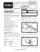
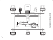
1. Using dimensions shown in figure 1. locate, mark
and drill a 1.00" dia. hole in each rear bumper bracket.
Figure 1
1. L.H. Rear bumper bracket
1
1.25" 2.00"
1.00" Dia.
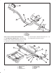
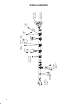
2. Using dimensions shown in figure 2. locate, mark
and drill a .750" dia. hole in carrier on front of traction
unit (Fig. 3).
Figure 2
1. Carrier
1
2.00"
.750" Dia.
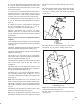
3. Insert appropriate size grommet into each drilled
hole (Fig. 3 & 4).