Form No. 3422-142 Rev B Universal Groomer Drive Kit Reelmaster® 3100-D 27-inch EdgeSeries Cutting Units Model No. 03240—Serial No. 318000001 and Up Installation Instructions This product complies with all relevant European directives. For details, please see the Declaration of Incorporation (DOI) at the back of this publication. Introduction Read this information carefully to learn how to operate and maintain your product properly and to avoid injury and product damage.
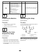
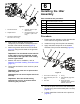
Loose Parts Use the chart below to verify that all parts have been shipped. Procedure 1 2 3 4 5 6 7 8 9 10 11 Description Qty. Use No parts required – Prepare the machine. No parts required – Gather the tools required for setup. No parts required – Determine which side the groomer should be installed on.
Procedure Description 12 Carriage bolt (5/16 x 2-1/4 inches), Part No. 3230-7—sold separately Carriage bolt (5/16 x 3-1/4 inches), Part No. 3230-13—sold separately Carriage bolt (5/16 x 4-1/2 inches), Part No. 3230-30—sold separately Spacer Flange nut (5/16 inch) Locknut (5/16 inch), Part No. 3296-47—sold separately Weight Small weight (Part No. 132-0734-03—sold separately) Use Qty. 1 1 1 1 2 1 Install the weights (rear cutting unit with groomer only, with rear grass basket).
5. Restrain the reel for removal; refer to Restraining the Reel for Removing Threaded Inserts (page 18). 6. Preparing the Cutting Unit Remove and discard the existing splined insert from each end of the reel shaft using the reel driveshaft tool (Part No. TOR4074 for the 7-inch reel). Refer to Figure 3.
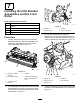
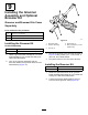
9. Remove the 2 flange-head bolts and washers securing the support rod, and remove the support rod (Figure 5). 5 Note: Retain the flange-head bolts. Installing the Weight Bracket and the Groomer Drive Box Parts needed for this procedure: 3 Weight bracket 6 Hex-socket, button-head bolt (3/8 x 3/4 inch) 2 Groomer drive box (left drive) 1 Groomer drive box (right drive) Procedure g192295 1. Figure 5 1. Flange-head bolts (2) 3.
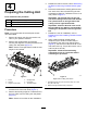
Installing the Idler Assembly Parts needed for this procedure: g228117 Figure 8 6 Hex-socket bolt (3/8 x 3/4 inch) 3 Pivot hub 3 O-ring 1 Idler assembly (left) 1. Internal reel-shaft 4. Groomer drive box (left drive shown) 2 Idler assembly (right) 2. Weight bracket 5. Hex-head (Torque to 135 to 150 N∙m (100 to 110 ft-lb)) 6 Jam locknut (3/8 inch) Procedure 3. Hex-socket, button-head bolt—3/8 x 3/4 inch (2) 3. 4.
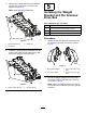
Installing the HOC Bracket Assemblies and the Front Roller Parts needed for this procedure: 6 Adjuster pin 6 Cotter pin 3 Left HOC bracket assembly 1. Adjuster pin 3. Cotter pin 3 Right HOC bracket assembly 2. Adjuster-arm rod 4. Groomer drive box 6 Flange locknut (3/8 with 5/8 inch hex) g232400 Figure 11 3. Procedure 1.
Installing the Groomer Drive Cap Parts needed for this procedure: 3 Cap Procedure Only for Universal Groomer assemblies with no rear roller brush kit installed: 1. Apply medium-strength cylindrical bonding retaining compound (such as Green Loctite 609®) around the snap ring groove and the outer diameter surface (Figure 14). 2. Install the cap as shown in Figure 14. g192299 Figure 13 1. Adjusting bolt 4. Flange nut 2. Locknut 5. Cap screw 3.
Installing the Groomer Assembly and Optional Broomer Kit Groomer and Broomer Kits Come Separately Parts needed for this procedure: 12 Bolt (1/4 x 1-1/2 inches) 12 Jam nut 12 Shaft clamp g240752 Figure 15 Installing the Groomer Kit Ordered Separately Model Number 03241 1. Drive-stub shaft 4. Shaft clamp (4) 2. Groomer assembly 5. Bolt (4) (Torque to 5-7 N∙m (46-60 in-lb)) 3. Jam nut (4) Groomer 27-inch Groomer Blade Cartridge Kit 1.
g032402 Figure 18 1. Brush 5. 2. Blade Loosely wrap the straps, as shown in Figure 16, around the groomer reel shaft and brushes, inserting the straps in the grooves in the brushes Figure 18. Position the brushes so that the straps are between the following blades: 2 and 3; 12 and 13; 23 and 24 or 24 and 25; 35 and 36, and 45 and 46. Important: You must wrap the straps around g032403 Figure 16 1. Strap buckle 3. Strap 2. Retaining nut 4.
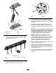
10 11 Installing the Weights Installing the Weights Groomer Only, with or without Front Grass Baskets and Rear Cutting Unit without Rear Grass Basket Groomer and Rear Roller Brush installed Parts needed for this procedure: Parts needed for this procedure: 6 Carriage bolt (5/16 x 3-1/2 inches) 6 Spacer 6 Carriage bolt (5/16 x 3-1/2 inches) 6 Flange nut (5/16 inch) 6 Spacer 12 Weight 6 Flange nut (5/16 inch) 18 Weight Procedure For cutting units with the groomer kit and the rear roller
Installing the Weights Rear Cutting Unit with Groomer Only, and with Rear Grass Basket) Parts needed for this procedure: 1 Carriage bolt (5/16 x 2-1/4 inches), Part No. 3230-7—sold separately 1 Carriage bolt (5/16 x 3-1/4 inches), Part No. 3230-13—sold separately g192301 Figure 21 Rear cutting unit with groomer and rear grass basket installed 1 Carriage bolt (5/16 x 4-1/2 inches), Part No. 3230-30—sold separately 2 Spacer 1 Flange nut (5/16 inch) 1.
Operation • The type of grass • The overall management program (i.e., irrigation, fertilizing, spraying, coring, overseeding, etc.) Introduction • Traffic Grooming is performed in the turf canopy above the soil level. Grooming promotes vertical growth of grass plants, reduces grain, and severs stolons, producing a denser turf. Grooming produces a more uniform and tighter playing surface for faster and truer action of the golf ball. • Stress periods (i.e.
Adjusting the Groomer Height 4. DANGER At 1 end of the groomer reel, measure the distance from the lowest tip of the groomer blade to the working surface (Figure 23). Turn the height adjuster knob (Figure 23) to raise or lower the groomer blade tip to the desired height. Contact with the reels or other moving parts can result in personal injury. • Before making any adjustments to the cutting units, disengage the reels, set the parking brake, shut off the engine, and remove the key.
Height-of-Cut (HOC) and Height-of-Groom (HOG) Recommended Range Height-of-Cut (mm) Height-of-Cut (inch) Number of Rear Roller Spacers Recommended HOG = HOC Groomer Engagement Recommended HOG = HOC Groomer Engagement (mm) (inch) 6.3 0.250 0 3.1 to 6.3 0.125 to 0.250 9.5 0.375 0 4.7 to 9.5 0.187 to 0.375 9.5 0.375 1 4.7 to 9.5 0.187 to 0.375 12.7 0.500 0 6.3 to 12.7 0.250 to 0.500 12.7 0.500 1 6.3 to 12.7 0.250 to 0.500 12.7 0.500 2 6.3 to 9.5 0.250 to 0.375 15.8 0.
Maintenance Testing the Groomer Performance DANGER Important: Improper or over-aggressive use of Contact with the reels or other moving parts can result in personal injury. the grooming reel (i.e., too deep or too frequent grooming) may cause unnecessary stress on the turf, leading to severe damage. Use the groomer cautiously. • Before making any adjustments to the cutting units, disengage the reels, engage the parking brake, shut off the engine, and remove the key.
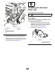
g241100 Figure 27 Right side groomer box shown g240875 Figure 25 1. Remove the drain plug from the drain port. 3. Loosen the air-vent plug. 1. Air-vent plug 3. Drain plug 2. Fill plug 2. Remove the fill plug from the fill port. 6. Rock the cutting unit back and forth to ensure complete drainage. When the oil is completely drained, place the cutting unit on a level surface. Removing the Groomer Drive Box 7. Install the drain plug. Note: Retain all removed parts for later installation 8.
Cleaning the Grooming Reel Service Interval: After each use Clean off the grooming reel after using it by spraying it with water. Do not direct the water stream directly at the groomer bearing seals. Do not permit the grooming reel to stand in water so that the components rust. Inspecting the Blades Service Interval: Before each use or daily Inspect the grooming-reel blades frequently for damage and wear. Straighten bent blades with a pliers and replace worn blades.
2. 3. Restraining the Reel Installing Threaded Inserts Insert a long-handled pry bar (recommended 3/8" x 12" with screwdriver handle) through the back of the cutting reel, closest to the side of the cutting unit that you will be torquing (Figure 30). 1. Insert a long-handled pry bar (recommended 3/8" x 12" with screwdriver handle) through the front of the cutting reel, closest to the side of the cutting unit that you will be torquing (Figure 31). 2.
Declaration of Incorporation The Toro Company, 8111 Lyndale Ave. South, Bloomington, MN, USA declares that the following unit(s) conform(s) to the directives listed, when installed in accordance with the accompanying instructions onto certain Toro models as indicated on the relevant Declarations of Conformity. Model No. 03240 Serial No.