Form No.
Revision History Revision Date -- 2015 A 02/2018 Updated Engine chapter. Added revision history. B 04/2018 Added VA02 planetary drive information. Revised bedknife installation procedure and painted/aluminum side plate cutting unit information. Added groomer chapters. C 06/2019 Updated rear axle service drawings. D 07/2020 Updated Electrical, Cutting Unit, Universal Groomer chapters and Foldout drawing. E 06/2021 Updated Hydraulic chapter.
Reader Comments The Toro Company Technical Assistance Center maintains a continuous effort to improve the quality and usefulness of its publications. To do this effectively, we encourage user feedback. Please comment on the completeness, accuracy, organization, usability, and readability of this manual by an e-mail to servicemanuals@toro.
NOTES _
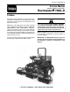
Part No. 15214SL Rev. E Service Manual (Models 03780/A and 03781) ReelmasterR 7000--D Preface The purpose of this publication is to provide the service technician with information for troubleshooting, testing and repair of major systems and components on the Reelmaster 7000--D. REFER TO THE TRACTION UNIT AND CUTTING UNIT OPERATOR’S MANUALS FOR OPERATING, MAINTENANCE AND ADJUSTMENT INSTRUCTIONS.
This page is intentionally blank.
2 -2 -2 -2 -- 1 1 2 3 Chapter 3 -- Yanmar Diesel Engine Chapter 7 -- Axles, Planetaries and Brakes Specifications . . . . . . . . . . . . . . . . . . . . . . . . . . . . . . 3 -- 2 General Information . . . . . . . . . . . . . . . . . . . . . . . . 3 -- 3 Service and Repairs . . . . . . . . . . . . . . . . . . . . . . . . 3 -- 9 YANMAR TNV (Tier 4) SERIES SERVICE MANUAL YANMAR TNV (Tier 4) SERIES TROUBLESHOOTING MANUAL Specifications . . . . . . . . . . . . . . . . . . . . . . . . . . . . . .
This page is intentionally blank.
Grooming Performance . . . . . . . . . . . . . . . . . . . . 11 -- 2 Troubleshooting . . . . . . . . . . . . . . . . . . . . . . . . . . . 11 -- 3 Service and Repairs . . . . . . . . . . . . . . . . . . . . . . . 11 -- 4 Chapter 12 -- Foldout Drawings Electrical Drawing Designations . . . . . . . . . . . . . 12 -- 2 Hydraulic Schematic . . . . . . . . . . . . . . . . . . . . . . . 12 -- 3 Electrical Schematics . . . . . . . . . . . . . . . . . . . . . . 12 -- 4 Wire Harness Drawings . . . . . . . . . . . .
This page is intentionally blank.
Safety Table of Contents GENERAL SAFETY INSTRUCTIONS . . . . . . . . . . . . Before Operating . . . . . . . . . . . . . . . . . . . . . . . . . . . . While Operating . . . . . . . . . . . . . . . . . . . . . . . . . . . . Maintenance and Service . . . . . . . . . . . . . . . . . . . . JACKING INSTRUCTIONS . . . . . . . . . . . . . . . . . . . . . SAFETY AND INSTRUCTION DECALS . . . . . . . . . .
General Safety Instructions The Reelmaster 7000 has been tested and certified by TORO for compliance with existing safety standards and specifications. Although hazard control and accident prevention partially are dependent upon the design and configuration of the machine, these factors are also dependent upon the awareness, concern and proper training of the personnel involved in the operation, transport, maintenance and storage of the machine.
1. The Traction Unit and Cutting Unit Operator’s Manuals provide information regarding the operation, general maintenance and maintenance intervals for your Reelmaster machine. Refer to these publications for additional information when servicing the machine. 2. Before servicing or making adjustments, lower cutting units, stop engine, set parking brake and remove key from the ignition switch. 3. Make sure machine is in safe operating condition by keeping all nuts, bolts and screws tight. 4.
Jacking Instructions CAUTION When changing attachments, tires or performing other service, use correct jacks and supports. Make sure machine is parked on a solid, level surface such as a concrete floor . Prior to raising machine, remove any attachments that may interfere with the safe and proper raising of the machine. Always chock or block wheels. Use jack stands to support the raised machine.
Safety Safety and Instruction Decals Numerous safety and instruction decals are affixed to the Reelmaster 7000. If any decal becomes illegible or damaged, install a new decal. Decal part numbers are listed in your Parts Catalog.
This page is intentionally blank.
Product Records and Maintenance Table of Contents PRODUCT RECORDS . . . . . . . . . . . . . . . . . . . . . . . . . MAINTENANCE . . . . . . . . . . . . . . . . . . . . . . . . . . . . . . EQUIVALENTS AND CONVERSIONS . . . . . . . . . . . Decimal and Millimeter Equivalents . . . . . . . . . . . . U.S. to Metric Conversions . . . . . . . . . . . . . . . . . . . TORQUE SPECIFICATIONS . . . . . . . . . . . . . . . . . . . Fastener Identification . . . . . . . . . . . . . . . . . . . . . . .
Equivalents and Conversions 0.
Recommended fastener torque values are listed in the following tables. For critical applications, as determined by Toro, either the recommended torque or a torque that is unique to the application is clearly identified and specified in this Service Manual. These Torque Specifications for the installation and tightening of fasteners shall apply to all fasteners which do not have a specific requirement identified in this Service Manual.
Standard Torque for Dry, Zinc Plated and Steel Fasteners (Inch Series) Thread Size Grade 1, 5 & 8 with Thin Height Nuts SAE Grade 1 Bolts, Screws, Studs & Sems with Regular Height Nuts (SAE J995 Grade 2 or Stronger Nuts) in−lb in−lb N−cm 10 + 2 13 + 2 147 + 23 # 6 − 32 UNC # 6 − 40 UNF # 8 − 32 UNC 13 + 2 25 + 5 # 10 − 24 UNC 30 + 5 SAE Grade 8 Bolts, Screws, Studs & Sems with Regular Height Nuts (SAE J995 Grade 5 or Stronger Nuts) in−lb N−cm in−lb N−cm 15 + 2 169 + 23 23 + 3 262 + 34
Thread Size Class 8.8 Bolts, Screws and Studs with Regular Height Nuts (Class 8 or Stronger Nuts) Class 10.9 Bolts, Screws and Studs with Regular Height Nuts (Class 10 or Stronger Nuts) M5 X 0.8 57 + 6 in−lb 644 + 68 N−cm 78 + 8 in−lb 881 + 90 N−cm M6 X 1.0 96 + 10 in−lb 1085 + 113 N−cm 133 + 14 in−lb 1503 + 158 N−cm M8 X 1.25 19 + 2 ft−lb 26 + 3 N−m 28 + 3 ft−lb 38 + 4 N−m M10 X 1.5 38 + 4 ft−lb 52 + 5 N−m 54 + 6 ft−lb 73 + 8 N−m M12 X 1.
Other Torque Specifications SAE Grade 8 Steel Set Screws Wheel Bolts and Lug Nuts Thread Size Recommended Torque Thread Size Square Head Hex Socket 1/4 − 20 UNC 140 + 20 in−lb 73 + 12 in−lb 5/16 − 18 UNC 215 + 35 in−lb 145 + 20 in−lb 3/8 − 16 UNC 35 + 10 ft−lb 18 + 3 ft−lb 1/2 − 13 UNC 75 + 15 ft−lb 50 + 10 ft−lb Recommended Torque** 7/16 − 20 UNF Grade 5 65 + 10 ft−lb 88 + 14 N−m 1/2 − 20 UNF Grade 5 80 + 10 ft−lb 108 + 14 N−m M12 X 1.25 Class 8.
Chapter 3 Yanmar Diesel Engine MODEL 03780 Table of Contents Reelmaster 7000−D Page 3 − 1 Yanmar Engine SPECIFICATIONS . . . . . . . . . . . . . . . . . . . . . . . . . . . . 2 GENERAL INFORMATION . . . . . . . . . . . . . . . . . . . . . 3 Operator’s Manuals . . . . . . . . . . . . . . . . . . . . . . . . . 3 Yanmar Service and Troubleshooting Manuals . . 3 Stopping the Engine . . . . . . . . . . . . . . . . . . . . . . . . . 3 Engine Electronic Control Unit (ECU) . . . . . . . . . .
Specifications Item Description Make / Designation Yanmar Model 4TNV86CT−DTR: 4−Cycle, 4 Cylinder, Water Cooled, Turbocharged, Tier 4 Diesel Engine Bore 3.386 in (86 mm) Stroke 3.543 in (90 mm) 127.5 in3 (2090 cc) Total Displacement 1 (closest to flywheel end) − 3 − 2 − 4 (farthest from flywheel) Firing Order Direction of Rotation Counterclockwise (viewed from flywheel) Fuel Diesel or Biodiesel (up to B20) Fuel with Ultra Low Sulfur Content Fuel Capacity 22 U.S.
General Information This Chapter gives information about specifications and repair of the diesel engine used in the Reelmaster 7000−D. General maintenance procedures are described in your Traction Unit Operator’s Manual. Information on engine troubleshooting, testing, disassembly and assembly is identified in the Yanmar Workshop Manual. Service and repair parts for Yanmar engines are supplied through your Authorized Toro Distributor.
Engine Electronic Control Unit (ECU) The Yanmar engine that powers your Reelmaster uses an Electronic Control Unit (ECU) for engine management and also to communicate with the Toro Electronic Controller (TEC) and the operator InfoCenter display on the machine. All wire harness electrical connectors should be plugged into the ECU before the machine ignition switch is moved from the OFF position to either the ON or START position. 1 The engine electrical components (e.g.
Yanmar Engine: Yanmar Engine The engine used on Reelmaster is a Yanmar TNV Series, turbocharged, diesel engine that complies with EPA Tier 4 emission regulations. Engine features include an electronic control unit (ECU) that controls a common rail fuel injection system with direct injection, water−cooled exhaust gas recirculation (EGR), an electronic governor, an exhaust system diesel oxidation catalyst (DOC) and an exhaust diesel particulate filter (DPF) with active regeneration.
Types of regeneration that are performed automatically (while the machine is operating) Type Conditions Description Passive Occurs during normal operation of the machine at high engine speed or high engine load. The DPF processes high heat exhaust gasses, oxidizing harmful emissions and incinerating soot to ash. The InfoCenter does not display an icon during passive regeneration.
Type Conditions Description Parked Occurs when exhaust back pressure in the DPF increases due to continued soot buildup. May be caused by prolonged operation at low engine speed, low engine load, or the use of incorrect fuel or engine oil. May occur if the InfoCenter is set to inhibit regen (preventing a Reset Regeneration) and machine operation is continued. Can be initiated when prompted by the engine ECU or after a minimum of 50 hours of engine operation.
Soot Accumulation If the types of regeneration that are performed automatically (while the machine is operating) are bypassed or not allowed to complete before shutting off the engine, soot will continue to accumulate in the soot filter. When enough soot accumulates, the engine ECU will generate an engine fault to prompt a parked or recovery regeneration. In addition to an engine fault appearing on the InfoCenter, the engine output power will be reduced.
Service and Repairs Air Cleaner System 17 16 15 RIGHT FRONT 13 3 2 12 Yanmar Engine 10 14 11 1 VACUATOR DIRECTION 19 18 4 8 5 9 6 7 16 to 19 in−lb (1.8 to 2.2 N−m) Figure 3 1. 2. 3. 4. 5. 6. 7. Air cleaner assembly Adapter Indicator Air cleaner strap Flat washer (2) Flat washer (2) Socket head screw (2) Reelmaster 7000−D 8. 9. 10. 11. 12. 13. Lock nut (2) Spring (2) Air cleaner outlet hose Hose clamp Hose clamp Air cleaner inlet hose Page 3 − 9 14. 15. 16. 17. 18. 19.
Removal (Fig. 3) 1. Park machine on a level surface, lower cutting units, stop engine, apply parking brake and remove key from the ignition switch. 2 2. Raise and support hood. 4 3. Remove air cleaner components as needed. 1 Installation (Fig. 3) IMPORTANT: Any leaks in the air filter system will cause serious engine damage. Make sure that all air cleaner components are in good condition and are properly secured during assembly. 3 5 1. Assemble air cleaner components. A.
Exhaust System 7 40 41 19 to 29 ft−lb (25 to 40 N−m) 39 37 8 18 11 17 31 36 38 26 34 25 32 10 5 16 20 15 27 25 12 34 28 27 30 Yanmar Emgine 33 to 40 ft−lb (45 to 55 N−m) 16 22 35 31 29 33 to 40 ft−lb (45 to 55 N−m) 33 18 4 9 16 23 18 1 14 18 3 18 23 15 44 21 23 16 13 RIGHT 42 FRONT 19 6 24 2 43 Figure 6 1. 2. 3. 4. 5. 6. 7. 8. 9. 10. 11. 12. 13. 14. 15.
Reelmaster 7000−D models that are powered by a diesel engine that complies with EPA Tier 4 emission regulations are equipped with an exhaust system that includes a diesel oxidation catalyst (DOC) and a diesel particulate filter (DPF). These exhaust components require service or component replacement at intervals identified in your Operator’s Manual.
Fuel System Thread Sealant 21 To Engine 8 19 17 21 8 8 20 15 Yanmar Engine 16 14 18 8 13 Return From Engine 1 8 3 4 2 23 5 24 7 6 RIGHT 9 FRONT 10 22 Thread Sealant 25 11 26 12 Figure 8 1. 2. 3. 4. 5. 6. 7. 8. 9. Fuel suction tube Fuel line clamp (2) Fuel hose (tank to pump) Return fitting Fuel hose (engine to tank) Fuel tank cap Bushing (2) Hose clamp (6) Fuel tank Reelmaster 7000−D 10. 11. 12. 13. 14. 15. 16. 17. 18.
Fuel Tank Removal (Fig. 8) DANGER Because diesel fuel is highly flammable, use caution when storing or handling it. Do not smoke while filling the fuel tank. Do not fill fuel tank while engine is running, hot or when machine is in an enclosed area. Always fill fuel tank outside and wipe up any spilled diesel fuel before starting the engine. Store fuel in a clean, safety−approved container and keep cap in place. Use diesel fuel for the engine only; not for any other purpose. 1.
Radiator/Hydraulic Oil Cooler 17 16 15 42 18 43 44 41 45 14 38 19 20 21 Yanmar Engine 13 1 45 22 34 3 44 37 9 41 42 43 40 33 2 36 5 39 32 8 30 31 35 7 5 6 4 7 6 RIGHT 11 10 27 24 FRONT 28 25 12 23 29 21 26 Figure 9 1. 2. 3. 4. 5. 6. 7. 8. 9. 10. 11. 12. 13. 14. 15.
Removal (Fig. 9) 1. Park machine on a level surface, lower cutting units, stop engine, engage parking brake and remove key from the ignition switch. 4 1 4 2. Remove hood from the machine (see Hood Removal in Chapter 8 − Chassis in this manual). 3. Remove air cleaner intake hose from air cleaner. 4. Remove flange head screws and flange nuts that secure plenum (item 13) to crossover plate. Remove plenum with air cleaner hose and drain hose attached. 5.
Installation (Fig. 9) 1. If hydraulic fittings were removed from oil cooler, lubricate and place new O−rings onto fittings. Install fittings into oil cooler openings using marks made during the removal process to properly orientate fittings (Fig. 11). Tighten fittings (see Hydraulic Fitting Installation in Chapter 5 − Hydraulic System in this manual). 3 2 4 5 1 6 2. If hydraulic plug was removed from oil cooler, place new O−ring on plug and install into oil cooler port (Fig. 11).
This page is intentionally left blank.
Engine 19 18 18 FRONT 14 Rear Lift Tab 12 13 22 6 20 21 Yanmar Engine RIGHT Front Lift Tab 5 4 11 6 5 15 9 16 8 2 7 17 10 9 8 7 10 9 11 3 8 11 1 5 23 9 8 5 6 6 7 10 9 7 24 10 9 Figure 13 1. 2. 3. 4. 5. 6. 7. 8. Mount bracket − left front Mount bracket − right front Mount bracket − left rear Mount bracket − right rear Lock washer (16) Cap screw (16) Engine mount (4) Flange head screw (7) Reelmaster 7000−D 9. 10. 11. 12. 13. 14. 15. 16.
Engine Removal (Fig. 13) 6 1. Park machine on a level surface, lower cutting units, stop engine, engage parking brake and remove key from the ignition switch. 5 2. Remove hood from the machine (see Hood Removal in Chapter 8 − Chassis in this manual). 2 7 3. Open battery box cover and disconnect negative battery cable first and then positive battery cable. 1 CAUTION Do not open radiator cap or drain coolant if the radiator or engine is hot. Pressurized, hot coolant can escape and cause burns.
13.Disconnect fuel supply and return hoses from injection pump (item 16 and 17). Cap fuel hoses and injector pump fittings to prevent contamination. 14.Support hydraulic pump assembly. Remove fasteners that secure piston (traction) pump assembly to engine (see Piston (Traction) Pump Assembly Removal in Chapter 5 − Hydraulic System in this manual). 15.Make sure all cable ties securing the wire harness, fuel lines and hydraulic hoses to the engine are removed.
9. Using notes taken during engine removal, secure wires with cable ties in proper locations. 6 10.Install engine cooling fan assembly and fan shrouds to machine (see Engine Cooling Fan Motor in Chapter 5 − Hydraulic System in this manual). 5 11. Install air cleaner assembly to the engine (see Air Cleaner Installation in this chapter). 2 7 12.If removed, install exhaust tailpipe. 1 13.Connect coolant hoses to the radiator. 14.Install plenum with air cleaner hose and drain hose attached.
Pump Adapter Plate 7 Loctite #242 (if reused) 17 to 21 ft−lb (23 to 28 N−m) Yanmar Engine 3 6 4 RIGHT Boss 1 FRONT 2 5 Loctite #242 (if reused) Figure 16 1. Flywheel plate 2. Hardened washer (8) 3. Spring coupler Reelmaster 7000−D 4. Cap screw with patch lock (8) 5. Cap screw with patch lock (8) Page 3 − 23 6. Hardened washer (8) 7.
Coupler Removal (Fig. 16) NOTE: The hydraulic pump assembly needs to be removed from engine before coupler can be removed. Engine Side Hydraulic Pump Side 1. If engine is in machine, remove hydraulic pump assembly (see Piston (Traction) Pump in Chapter 5 − Hydraulic System in this manual). 1 2. Remove flywheel plate and spring coupler from engine. Coupler Installation (Fig. 16) 1. Position spring coupler to engine flywheel and align mounting holes.
Chapter 4 Kubota Diesel Engine MODEL 03781 Table of Contents Reelmaster 7000−D Page 4 − 1 Kubota Engine SPECIFICATIONS . . . . . . . . . . . . . . . . . . . . . . . . . . . . 2 GENERAL INFORMATION . . . . . . . . . . . . . . . . . . . . . 3 Operator’s Manual . . . . . . . . . . . . . . . . . . . . . . . . . . 3 SERVICE AND REPAIRS . . . . . . . . . . . . . . . . . . . . . . 4 Air Filter System . . . . . . . . . . . . . . . . . . . . . . . . . . . . 4 Exhaust System . . . . . . . . . . . . . . . . . .
Specifications Item Description Make / Designation Kubota Model V2403−M−DI−E3B 4−Cycle, 4 Cylinder, Liquid Cooled, Diesel Engine Bore 3.425” (87.0 mm) Stroke 4.031” (102.4 mm) Total Displacement 148.5 in3 (2434 cc) Firing Order 1 (closest to gear case end) − 3 − 4 (closest to flywheel end) − 2 Combustion Chamber Spherical Type (E−TVCS) Compression Ratio 23.
General Information This Chapter gives information about specifications and repair of the Kubota diesel engine used in the Reelmaster 7000−D Model 03781. General maintenance procedures are described in your Traction Unit Operator’s Manual. Information on engine troubleshooting, testing, disassembly and assembly is identified in the Kubota Workshop Manual, Diesel Engine, 03−M−DI−E3B. Most repairs and adjustments require tools which are commonly available in many service shops.
Service and Repairs Air Filter System RIGHT FRONT 19 12 to 15 in−lb (1.4 to 1.6 N−m) 18 12 12 11 17 16 13 10 Vacuator Direction 9 14 15 6 1 8 7 2 5 4 3 6 Figure 1 1. 2. 3. 4. 5. 6. 7. Battery support Bracket Flange head screw (8) Flange nut (8) Support bracket Cap screw (4) Flange nut (4) Kubota Diesel Engine 8. 9. 10. 11. 12. 13. Air cleaner strap Cap screw (2) Air cleaner assembly Service indicator Hose clamp Hose clamp Page 4 − 4 14. 15. 16. 17. 18. 19.
Removal (Fig. 1) 1. Park machine on a level surface, lower cutting units, stop engine, apply parking brake and remove key from the ignition switch. 2 4 2. Raise and support hood. 1 3. Remove air cleaner components as needed. Installation (Fig. 1) 3 IMPORTANT: Any leaks in the air filter system will cause serious engine damage. Make sure that all air cleaner components are in good condition and are properly secured during assembly. 5 Figure 2 A.
Exhaust System 8 13 1 12 5 3 7 10 14 4 11 6 2 9 RIGHT FRONT Figure 4 1. 2. 3. 4. 5. Muffler Flange head screw (2) Flange head screw (4) Muffler clamp Tailpipe Kubota Diesel Engine 6. 7. 8. 9. 10. RH engine mount Flat washer Cap screw Muffler bracket Muffler gasket Page 4 − 6 11. 12. 13. 14.
Installation (Fig. 4) CAUTION The muffler and exhaust pipe may be hot. T o avoid possible burns, allow the engine and exhaust system to cool before working on the muffler. 1. Park machine on a level surface, lower cutting units, stop engine, engage parking brake and remove key from the ignition switch. 2. Raise and support hood. 3. Remove muffler and/or muffler bracket from the engine as necessary.
Fuel System Thread Sealant 22 8 20 19 Thread Sealant 16 22 18 8 21 To Engine 17 8 19 8 13 14 15 28 Return From Engine 1 8 3 4 2 5 24 25 7 6 9 RIGHT FRONT 10 23 Thread Sealant 26 11 27 12 Figure 5 1. 2. 3. 4. 5. 6. 7. 8. 9. 10. Fuel suction tube Fuel line clamp (2) Fuel hose (tank to pump) Return fitting Fuel hose (engine to tank) Fuel tank cap Bushing (2) Hose clamp (6) Fuel tank Cap screw (2) Kubota Diesel Engine 11. 12. 13. 14. 15. 16. 17. 18. 19.
Fuel Tank Removal (Fig. 5) Because diesel fuel is flammable, use caution when storing or handling it. Do not smoke while filling the fuel tank. Do not fill fuel tank while engine is running, hot or when machine is in an enclosed area. Always fill fuel tank outside and wipe up any spilled diesel fuel before starting the engine. Store fuel in a clean, safety−approved container and keep cap in place. Use diesel fuel for the engine only; not for any other purpose. 1.
Prime Fuel System 2 1. Park machine on a level surface, lower cutting units, stop engine, and engage parking brake. Make sure fuel tank is at least half full. 2. Release hood latch and open hood. 1 DANGER Under certain conditions, diesel fuel and fuel vapors are highly flammable and explosive. A fire or explosion from fuel can burn you and others and can cause property damage. • Fill the fuel tank outdoors, in an open area, when the engine is cold. Wipe up any fuel that spills.
Bleed Air From Injectors IMPORTANT: This procedure should be used only if the fuel system has been purged of air through normal priming procedures (see Priming Fuel System in this chapter) and engine will not start. 1 1. Park machine on a level surface, lower cutting units, stop engine, and engage parking brake. DANGER • Fill the fuel tank outdoors, in an open area, when the engine is cold. Wipe up any fuel that spills. • Never fill the fuel tank inside an enclosed trailer.
Radiator/Hydraulic Oil Cooler 17 16 15 42 18 43 44 41 45 14 38 13 19 20 21 1 45 22 34 3 44 43 37 9 41 42 40 33 2 36 39 5 30 32 31 8 35 5 6 4 7 6 7 RIGHT 10 29 21 27 24 23 11 FRONT 28 12 25 26 Figure 9 1. 2. 3. 4. 5. 6. 7. 8. 9. 10. 11. 12. 13. 14. 15.
Removal (Fig. 9) 1. Park machine on a level surface, lower cutting units, stop engine, engage parking brake and remove key from the ignition switch. 4 1 4 2. Remove hood from the machine (see Hood Removal in Chapter 8 − Chassis in this manual). 3. Remove air cleaner intake hose from air cleaner. 4. Remove flange head screws and flange nuts that secure plenum (item 13) to crossover plate. Remove plenum with air cleaner hose and drain hose attached. 5 7 3 6 5.
Installation (Fig. 9) 3 2 1. If hydraulic fittings were removed from oil cooler, lubricate and place new O−rings onto fittings. Install fittings into oil cooler openings using marks made during the removal process to properly orientate fittings (Fig. 11). Tighten fittings (see Hydraulic Fitting Installation in Chapter 5 − Hydraulic System in this manual). 4 5 1 6 2. If hydraulic plug was removed from oil cooler, place new O−ring on plug and install into oil cooler port (Fig. 11). Thread sealant 3.
Kubota Engine This page is intentionally left blank.
Engine 10 9 Rear Lift Tab 8 10 1 11 3 4 7 6 12 2 24 17 13 25 18 4 16 5 15 14 RIGHT FRONT 6 3 7 20 22 23 21 19 Figure 13 1. 2. 3. 4. 5. 6. 7. 8. 9. Engine Mount bracket − left rear Cap screw (5) Lock washer (5) Mount bracket − left front Lock washer (4) Cap screw (4) Mount bracket − right rear Muffler bracket Kubota Diesel Engine 10. 11. 12. 13. 14. 15. 16. 17.
Engine Removal (Fig. 13) 6 1. Park machine on a level surface, lower cutting units, stop engine, engage parking brake and remove key from the ignition switch. 5 2. Remove hood from the machine (see Hood Removal in Chapter 8 − Chassis in this manual). 2 7 3. Open battery box cover and disconnect negative battery cable first and then positive battery cable. 1 CAUTION Do not open radiator cap or drain coolant if the radiator or engine is hot. Pressurized, hot coolant can escape and cause burns.
14.Disconnect fuel supply and return hose from injection pump (Fig. 15). Cap fuel hoses and injector pump fittings to prevent contamination. 5 15.Remove throttle cable from engine (Fig. 15): A. Remove lock nut that secures throttle cable swivel to speed control lever. 1 B. Loosen cable clamp and remove throttle cable from under clamp. 3 2 C. Position throttle cable away from the engine. IMPORTANT: The hydraulic pump assembly can remain in machine during engine removal.
7. Connect throttle cable to engine (Fig. 16): 5 A. Secure throttle cable swivel to speed control lever with lock nut. B. Place throttle cable under cable clamp. C. Adjust throttle cable position in cable clamp so that engine governor lever contacts the high speed stop bolt at the same time that the throttle lever contacts the end of the slot in the control console. 1 2 3 D. Tighten cable clamp to secure throttle cable. 9.
16.Connect air cleaner intake hose to air cleaner. 22.Check and adjust engine oil level as needed. 17.Secure coolant reservoir bracket with reservoir to machine frame (Fig. 17). 23.Check and adjust hydraulic oil level as needed. 18.Connect coolant reservoir hose to the radiator (Fig. 17). 19.Make sure radiator draincock is closed and fill radiator and reservoir with coolant. 20.
Kubota Engine This page is intentionally left blank.
Pump Adapter Plate 1 2 RIGHT FRONT Loctite #242 (if reused) 29 to 33 ft−lb (40 to 44 N−m) 5 4 6 3 Boss 4 7 Loctite #242 (if reused) Figure 18 1. Bolt 2. Lock washer 3. Flywheel plate Kubota Diesel Engine 4. Hardened washer (14) 5. Spring coupler Page 4 − 22 6. Cap screw with patch lock (6) 7.
Coupler Removal (Fig. 18) NOTE: The hydraulic pump assembly needs to be removed from engine before coupler can be removed. Engine Side Hydraulic Pump Side 1. If engine is in machine, remove hydraulic pump assembly (see Piston (Traction) Pump Removal in Chapter 5 − Hydraulic System in this manual). 1 2. Remove flywheel plate and spring coupler from engine. Coupler Installation (Fig. 18) 1. Position spring coupler to engine flywheel and align mounting holes.
This page is intentionally blank.
Chapter 5 Hydraulic System SPECIFICATIONS . . . . . . . . . . . . . . . . . . . . . . . . . . . . 2 GENERAL INFORMATION . . . . . . . . . . . . . . . . . . . . . 3 Operator’s Manual . . . . . . . . . . . . . . . . . . . . . . . . . . 3 Hydraulic Component Locations . . . . . . . . . . . . . . 3 Relieving Hydraulic System Pressure . . . . . . . . . . 4 Traction Circuit Component Failure . . . . . . . . . . . . 4 Towing Traction Unit . . . . . . . . . . . . . . . . . . . . . . . . . 5 Hydraulic Hoses . . . .
Specifications Item Description Piston (Traction) Pump Eaton servo controlled variable displacement piston pump (Model 72400) 3.00 in3 (49.2 cc) 5000 PSI (345 bar) 5000 PSI (345 bar) Maximum Displacement (per revolution) System Relief Pressure: Forward System Relief Pressure: Reverse Charge Pressure 207 PSI (14.3 bar) Front Wheel Motors Displacement (per revolution) Danfoss 2−Position Axial Piston Motors 1.83 in3 (30 cc) Maximum / 0.89 in3 (14.
General Information Operator’s Manual The Operator’s Manuals provide information regarding the operation, general maintenance and maintenance intervals for your Reelmaster machine. Refer to both the Traction Unit Operator’s Manual and the Cutting Unit Operator’s Manual for additional information when servicing the machine. Hydraulic Component Locations 9 10 11 12 13 14 Hydraulic System 5 1 2 3 4 RIGHT FRONT 8 7 6 5 Figure 20 1. 2. 3. 4. 5.
Relieving Hydraulic System Pressure Before disconnecting or performing any work on the hydraulic system, pressure in all of the hydraulic circuits must be relieved. 1. Park machine on a level surface, lower cutting units fully, set the reel enable/disable switch to the OFF position, stop engine and apply parking brake. 2. Move the traction pedal in both forward and reverse directions (relieves pressure in traction circuit). 3.
Towing Traction Unit IMPORTANT: If towing limits are exceeded, severe damage to the piston pump may occur. 1 If it becomes necessary to tow (or push) the machine, tow (or push) in a forward direction, at a speed below 3 mph (4.8 kph) and for a distance less than 1/4 mile (0.4 km). The piston (traction) pump is equipped with a bypass valve that needs to be turned 90o for towing (Fig. 1). Do not turn bypass valve when engine is running.
Hydraulic Hoses Hydraulic hoses are subject to extreme conditions such as pressure differentials during operation and exposure to weather, sun, chemicals, very warm storage conditions or mishandling during operation and maintenance. These conditions can cause hose damage and deterioration. Some hoses are more susceptible to these conditions than others.
Hydraulic Hose and Tube Installation (O−Ring Face Seal Fitting) C. Use a second wrench to tighten the nut to the correct Flats From Wrench Resistance (F.F.W.R.). The markings on the nut and fitting body will verify that the connection has been properly tightened. 1. Make sure threads and sealing surfaces of the hose/ tube and the fitting are free of burrs, nicks, scratches or any foreign material. 2.
Hydraulic Fitting Installation (SAE Straight Thread O−Ring Fitting into Component Port) Non−Adjustable Fitting (Fig. 7) 1. Make sure all threads and sealing surfaces of fitting and component port are free of burrs, nicks, scratches or any foreign material. 5. If a torque wrench is not available, or if space at the port prevents use of a torque wrench, an alternate method of assembly is the Flats From Finger Tight (F.F.F.T.) method. 2.
Adjustable Fitting (Fig. 9) 1. Make sure all threads and sealing surfaces of fitting and component port are free of burrs, nicks, scratches or any foreign material. 2. As a preventative measure against leakage, it is recommended that the O−ring be replaced any time the connection is opened. Lock Nut 3. Lightly lubricate the O−ring with clean hydraulic oil. Fitting threads should be clean with no lubricant applied. Back−up Washer 4. Turn back the lock nut as far as possible.
This page is intentionally blank.
Reelmaster 7000- D SP1 MV1 Page 5 - 11 P1 T1 3000 psi LC1 110 psi CV1 50 psi RV1 .040 OR1 M2 T2 RV2 3000 psi .040 OR2 M4 1450 psi #2 1.6 CID P2 SP2 MV2 M3 RETURN FILTER OIL COOLER LC2 110 psi CV2 1450 psi #5 1.6 CID G2 REAR 1450 psi #3 1.6 CID 12.1 GPM M2 P1 PRV CV 12.1 GPM FAN CONTROL MANIFOLD G2 G1 S1 M1 0.
Hydraulic System SP1 MV1 MANIFOLD MOW CONTROL G1 M1 P1 LC1 110 psi CV1 50 psi RV1 .040 OR1 M2 T1 T2 RV2 3000 psi .040 OR2 M4 Page 5 − 12 1450 psi #2 1.6 CID P2 SP2 MV2 M3 RETURN FILTER OIL COOLER LC2 110 psi CV2 1450 psi #5 1.6 CID 3000 psi 1450 psi 1450 psi FRONT #1 1.6 CID #4 1.6 CID REEL MOTORS G2 REAR 1450 psi #3 1.6 CID S1 12.1 GPM M2 P1 PRV CV 12.1 GPM FAN CONTROL MANIFOLD G2 G1 M1 0.51 CID FAN MOTOR 6.1 CIR FD STRAINER P5 0.56 CID P4 0.
Traction Circuit: LOW Speed (Mow) Front wheel motors and the rear axle motor are positive, dual displacement motors. The dual displacement feature allows operation in either a LOW (mow) or HI (transport) speed range. The motors are spring biased to maximum displacement for LOW speeds, and are hydraulically shifted to minimum displacement for HI speeds. The rear axle motor includes a flushing valve to help cool the traction circuit oil.
Hydraulic System Page 5 − 14 Reelmaster 7000−D SP1 MV1 MANIFOLD MOW CONTROL G1 M1 1450 psi 1450 psi P1 T1 3000 psi LC1 CV2 T2 RV2 3000 psi .040 OR2 M4 SP2 MV2 P2 RETURN FILTER #2 1.6 CID 1450 psi M3 REEL MOTORS OIL COOLER LC2 110 psi 1450 psi #5 1.6 CID 110 psi CV1 50 psi RV1 .040 OR1 M2 FRONT #1 1.6 CID #4 1.6 CID G2 REAR 1450 psi #3 1.6 CID 12.1 GPM M2 P1 PRV CV 12.1 GPM FAN CONTROL MANIFOLD G2 G1 S1 M1 0.51 CID FAN MOTOR 6.
Traction Circuit: HI Speed (Transport) Front wheel motors and the rear axle motor are positive, dual displacement motors. The dual displacement feature allows operation in either a LOW (mow) or HI (transport) speed range. The motors are spring biased to maximum displacement for LOW speeds, and are hydraulically shifted to minimum displacement for HI speeds. The rear axle motor includes a flushing valve to help cool the traction circuit oil.
Hydraulic System Page 5 − 16 Reelmaster 7000−D SP1 MV1 MOW CONTROL MANIFOLD G1 M1 1450 psi 1450 psi P1 T1 3000 psi LC1 CV2 T2 RV2 3000 psi .040 OR2 M4 #2 1.6 CID 1450 psi P2 SP2 MV2 M3 RETURN FILTER OIL COOLER LC2 110 psi 1450 psi #5 1.6 CID 110 psi CV1 50 psi RV1 .040 OR1 M2 FRONT #1 1.6 CID #4 1.6 CID REEL MOTORS G2 REAR 1450 psi #3 1.6 CID S1 12.1 GPM M2 P1 PRV CV 12.1 GPM FAN CONTROL MANIFOLD G2 G1 M1 0.51 CID FAN MOTOR 6.
Mow Circuit A single mow control manifold is used to control flow from the two (2) pump sections. The manifold includes cartridge valves for control of each of the two (2) pump circuits. Each mow circuit includes a solenoid controlled proportional valve (SP1 and SP2), a logic cartridge (LC1 and LC2) and a circuit relief cartridge (RV1 and RV2). All cutting reel motors are equipped with cross over relief valves to prevent hydraulic component damage in case a cutting reel should stall.
Hydraulic System Page 5 − 18 Reelmaster 7000−D SP1 MV1 MOW CONTROL MANIFOLD G1 M1 1450 psi 1450 psi P1 T1 3000 psi LC1 CV2 T2 RV2 3000 psi .040 OR2 M4 #2 1.6 CID 1450 psi P2 SP2 MV2 M3 RETURN FILTER OIL COOLER LC2 110 psi 1450 psi #5 1.6 CID 110 psi CV1 50 psi RV1 .040 OR1 M2 FRONT #1 1.6 CID #4 1.6 CID REEL MOTORS G2 REAR 1450 psi #3 1.6 CID S1 12.1 GPM M2 P1 PRV CV 12.1 GPM FAN CONTROL MANIFOLD G2 G1 M1 0.51 CID FAN MOTOR 6.
Steering Circuit With the steering wheel in the neutral position and the engine running, pump section P4 flow enters the steering control valve at the P port and goes through the steering control spool valve, bypassing the rotary meter and steering cylinder. Flow leaves the control valve through the E port to the traction charge circuit.
Hydraulic System Page 5 − 20 Reelmaster 7000−D SP1 MV1 MANIFOLD MOW CONTROL G1 M1 1450 psi 1450 psi P1 T1 3000 psi LC1 CV2 T2 RV2 3000 psi .040 OR2 M4 #2 1.6 CID 1450 psi P2 SP2 MV2 M3 RETURN FILTER OIL COOLER LC2 110 psi 1450 psi #5 1.6 CID 110 psi CV1 50 psi RV1 .040 OR1 M2 FRONT #1 1.6 CID #4 1.6 CID REEL MOTORS 1450 psi G2 REAR #3 1.6 CID S1 12.1 GPM M2 P1 PRV CV 12.1 GPM FAN CONTROL MANIFOLD G2 G1 M1 0.51 CID FAN MOTOR 6.
Lower Cutting Units A four section gear pump is coupled to the piston (traction) pump. Gear pump section P4 supplies hydraulic flow to both the lift control manifold and the steering control valve. Hydraulic flow from this pump section is delivered to the circuits through a proportional flow divider located in the fan control manifold. Maximum lift/lower circuit pressure is limited to 1700 PSI (117 bar) by a relief valve (RV1) in the lift control manifold.
Hydraulic System Page 5 − 22 Reelmaster 7000−D SP1 MV1 MANIFOLD MOW CONTROL G1 M1 1450 psi 1450 psi P1 T1 3000 psi LC1 CV2 T2 RV2 3000 psi .040 OR2 M4 #2 1.6 CID 1450 psi P2 SP2 MV2 M3 RETURN FILTER OIL COOLER LC2 110 psi 1450 psi #5 1.6 CID 110 psi CV1 50 psi RV1 .040 OR1 M2 FRONT #1 1.6 CID #4 1.6 CID REEL MOTORS G2 REAR 1450 psi #3 1.6 CID S1 12.1 GPM M2 P1 PRV CV 12.1 GPM FAN CONTROL MANIFOLD G2 G1 M1 0.51 CID FAN MOTOR 6.
Raise Cutting Units A four section gear pump is coupled to the piston (traction) pump. Gear pump section P4 supplies hydraulic flow to both the lift control manifold and the steering control valve. Hydraulic flow from this pump section is delivered to the circuits through a proportional flow divider located in the fan control manifold. Maximum lift/lower circuit pressure is limited to 1700 PSI (117 bar) by a relief valve (RV1) in the lift control manifold.
Hydraulic System Page 5 − 24 Reelmaster 7000−D SP1 MV1 MOW CONTROL MANIFOLD G1 M1 1450 psi 1450 psi P1 T1 3000 psi LC1 CV2 T2 RV2 3000 psi .040 OR2 M4 #2 1.6 CID 1450 psi P2 SP2 MV2 M3 RETURN FILTER OIL COOLER LC2 110 psi 1450 psi #5 1.6 CID 110 psi CV1 50 psi RV1 .040 OR1 M2 FRONT #1 1.6 CID #4 1.6 CID REEL MOTORS G2 REAR 1450 psi #3 1.6 CID S1 12.1 GPM M2 P1 PRV CV 12.1 GPM FAN CONTROL MANIFOLD G2 G1 M1 0.51 CID FAN MOTOR 6.
Engine Cooling Fan Circuit The fan control manifold controls the operation of the hydraulic motor that drives the engine cooling fan in addition to including the flow divider (FD) for the steering and lift circuits. The electronically controlled proportional relief valve (PRV) in the fan control manifold TS port controls the oil flow to the fan motor. The fan control manifold controls the speed and direction of the fan motor based on electrical output from the Toro Electronic Controller (TEC).
Special Tools Order the following special tools from your Toro Distributor. Hydraulic Pressure Test Kit Use to take various pressure readings for diagnostic tests. Quick disconnect fittings provided attach directly to mating fittings on machine test ports without tools. A high pressure hose is provided for remote readings. Contains one each: 1000 PSI (70 Bar), 5000 PSI (350 Bar) and 10000 PSI (700 Bar) gauges. Use gauges as recommended in Testing section of this chapter.
40 GPM Hydraulic Tester (Pressure and Flow) Use to test hydraulic circuits and components for flow and pressure capacities as recommended in the Testing section of this chapter. This tester includes the following: 1. LOAD VALVE: A simulated working load is created in the circuit by turning the valve to restrict flow. 2. PRESSURE GAUGE: Glycerine filled 0 to 5000 PSI gauge to provide operating circuit pressure. 3.
High Flow Hydraulic Filter Kit The high flow hydraulic filter kit is designed with large flow (40 GPM/150 LPM) and high pressure (5000 PSI/345 bar) capabilities. This kit provides for bi−directional filtration which prevents filtered debris from being allowed back into the circuit regardless of flow direction. If a component failure occurs in the closed loop traction circuit, contamination from the failed part will remain in the circuit until removed.
Measuring Container Use this container for doing hydraulic motor efficiency testing (motors with case drain lines only). Measure efficiency of a hydraulic motor by restricting the outlet flow from the motor and measuring leakage from the case drain line while the motor is pressurized by the hydraulic system. The table in Figure 25 provides gallons per minute (GPM) conversion for measured milliliter or ounce motor case drain leakage.
Remote Starter Switch After flushing the hydraulic system or replacing a hydraulic component (e.g. gear pump, piston pump, wheel motor), it is necessary to prime the hydraulic pumps. A remote starter switch (Fig. 27) can be used for this purpose. Obtain a remote starter switch locally. IMPORTANT: When using a remote starter switch, it is highly recommended to include a 20 amp in−line fuse between the battery and switch connector for circuit protection.
Troubleshooting The charts that follow contain information to assist in hydraulic system troubleshooting. There may possibly be more than one cause for a machine malfunction. Refer to the Testing section of this Chapter for precautions and specific testing procedures.
Traction Circuit Problems When troubleshooting traction circuit problems, if a problem exists in both low (mow) and high (transport) speeds, consider a faulty component that affects the entire traction circuit (e.g. charge circuit, traction circuit relief valves, piston pump). If the problem exists in LOW speed (mow) but not in HI speed (transport), consider a problem that only exists in mow (e.g. swashplate components in front wheel or rear axle motor, solenoid valve in HI/LOW range manifold).
ÁÁÁÁÁÁÁÁÁÁÁÁÁÁÁÁÁÁÁÁÁÁÁÁÁÁÁÁÁÁÁÁÁÁÁ ÁÁÁÁÁÁÁÁÁÁÁÁÁÁÁÁÁÁÁÁÁÁÁÁÁÁÁÁÁÁÁÁÁÁÁ ÁÁÁÁÁÁÁÁÁÁÁÁÁÁÁÁÁÁÁÁÁÁÁÁÁÁÁÁÁÁÁÁÁÁÁ ÁÁÁÁÁÁÁÁÁÁÁÁÁÁÁÁÁÁÁÁÁÁÁÁÁÁÁÁÁÁÁÁÁÁÁ ÁÁÁÁÁÁÁÁÁÁÁÁÁ ÁÁÁÁÁÁÁÁÁÁÁÁÁÁÁÁÁÁÁÁÁÁ ÁÁÁÁÁÁÁÁÁÁÁÁÁÁÁÁÁÁÁÁÁÁÁÁÁÁÁÁÁÁÁÁÁÁÁ ÁÁÁÁÁÁÁÁÁÁÁÁÁ ÁÁÁÁÁÁÁÁÁÁÁÁÁÁÁÁÁÁÁÁÁÁ ÁÁÁÁÁÁÁÁÁÁÁÁÁÁÁÁÁÁÁÁÁÁÁÁÁÁÁÁÁÁÁÁÁÁÁ ÁÁÁÁÁÁÁÁÁÁÁÁÁ ÁÁÁÁÁÁÁÁÁÁÁÁÁÁÁÁÁÁÁÁÁÁ ÁÁÁÁÁÁÁÁÁÁÁÁÁÁÁÁÁÁÁÁÁÁÁÁÁÁÁÁÁÁÁÁÁÁÁ ÁÁÁÁÁÁÁÁÁÁÁÁÁÁÁÁÁÁÁÁÁÁÁÁÁÁÁÁÁÁÁÁÁÁÁ ÁÁÁÁÁÁÁÁÁÁÁÁÁ ÁÁÁÁÁÁÁÁÁÁÁÁÁÁÁÁÁÁÁÁÁÁ ÁÁÁÁÁÁÁÁÁÁÁÁÁÁÁÁÁÁÁÁÁÁÁÁÁÁÁÁÁÁÁÁÁÁÁ ÁÁÁÁÁÁÁÁÁÁÁÁÁÁÁÁÁÁÁÁÁÁÁÁÁÁÁÁÁÁÁÁÁÁÁ ÁÁÁÁ
ÁÁÁÁÁÁÁÁÁÁÁÁÁÁÁÁÁÁÁÁÁÁÁÁÁÁÁÁÁÁÁÁÁÁÁ ÁÁÁÁÁÁÁÁÁÁÁÁÁÁÁÁÁÁÁÁÁÁÁÁÁÁÁÁÁÁÁÁÁÁÁ ÁÁÁÁÁÁÁÁÁÁÁÁÁÁÁÁÁÁÁÁÁÁÁÁÁÁÁÁÁÁÁÁÁÁÁ ÁÁÁÁÁÁÁÁÁÁÁÁÁÁÁÁÁÁÁÁÁÁÁÁÁÁÁÁÁÁÁÁÁÁÁ ÁÁÁÁÁÁÁÁÁÁÁÁÁ ÁÁÁÁÁÁÁÁÁÁÁÁÁÁÁÁÁÁÁÁÁÁ ÁÁÁÁÁÁÁÁÁÁÁÁÁÁÁÁÁÁÁÁÁÁÁÁÁÁÁÁÁÁÁÁÁÁÁ ÁÁÁÁÁÁÁÁÁÁÁÁÁ ÁÁÁÁÁÁÁÁÁÁÁÁÁÁÁÁÁÁÁÁÁÁ ÁÁÁÁÁÁÁÁÁÁÁÁÁÁÁÁÁÁÁÁÁÁÁÁÁÁÁÁÁÁÁÁÁÁÁ ÁÁÁÁÁÁÁÁÁÁÁÁÁ ÁÁÁÁÁÁÁÁÁÁÁÁÁÁÁÁÁÁÁÁÁÁ ÁÁÁÁÁÁÁÁÁÁÁÁÁÁÁÁÁÁÁÁÁÁÁÁÁÁÁÁÁÁÁÁÁÁÁ ÁÁÁÁÁÁÁÁÁÁÁÁÁÁÁÁÁÁÁÁÁÁÁÁÁÁÁÁÁÁÁÁÁÁÁ Mow Circuit Problems (Continued) Problem Possible Cause Cutting unit stops under load.
ÁÁÁÁÁÁÁÁÁÁÁÁÁÁÁÁÁÁÁÁÁÁÁÁÁÁÁÁÁÁÁÁÁÁÁ ÁÁÁÁÁÁÁÁÁÁÁÁÁÁÁÁÁÁÁÁÁÁÁÁÁÁÁÁÁÁÁÁÁÁÁ ÁÁÁÁÁÁÁÁÁÁÁÁÁÁÁÁÁÁÁÁÁÁÁÁÁÁÁÁÁÁÁÁÁÁÁ ÁÁÁÁÁÁÁÁÁÁÁÁÁÁÁÁÁÁÁÁÁÁÁÁÁÁÁÁÁÁÁÁÁÁÁ ÁÁÁÁÁÁÁÁÁÁÁÁÁ ÁÁÁÁÁÁÁÁÁÁÁÁÁÁÁÁÁÁÁÁÁÁ ÁÁÁÁÁÁÁÁÁÁÁÁÁÁÁÁÁÁÁÁÁÁÁÁÁÁÁÁÁÁÁÁÁÁÁ ÁÁÁÁÁÁÁÁÁÁÁÁÁ ÁÁÁÁÁÁÁÁÁÁÁÁÁÁÁÁÁÁÁÁÁÁ ÁÁÁÁÁÁÁÁÁÁÁÁÁÁÁÁÁÁÁÁÁÁÁÁÁÁÁÁÁÁÁÁÁÁÁ ÁÁÁÁÁÁÁÁÁÁÁÁÁ ÁÁÁÁÁÁÁÁÁÁÁÁÁÁÁÁÁÁÁÁÁÁ ÁÁÁÁÁÁÁÁÁÁÁÁÁÁÁÁÁÁÁÁÁÁÁÁÁÁÁÁÁÁÁÁÁÁÁ ÁÁÁÁÁÁÁÁÁÁÁÁÁÁÁÁÁÁÁÁÁÁÁÁÁÁÁÁÁÁÁÁÁÁÁ ÁÁÁÁÁÁÁÁÁÁÁÁÁ ÁÁÁÁÁÁÁÁÁÁÁÁÁÁÁÁÁÁÁÁÁÁ ÁÁÁÁÁÁÁÁÁÁÁÁÁÁÁÁÁÁÁÁÁÁÁÁÁÁÁÁÁÁÁÁÁÁÁ ÁÁÁÁÁÁÁÁÁÁÁÁÁÁÁÁÁÁÁÁÁÁÁÁÁÁÁÁÁÁÁÁÁÁÁ ÁÁÁÁ
ÁÁÁÁÁÁÁÁÁÁÁÁÁÁÁÁÁÁÁÁÁÁÁÁÁÁÁÁÁÁÁÁÁÁÁ ÁÁÁÁÁÁÁÁÁÁÁÁÁÁÁÁÁÁÁÁÁÁÁÁÁÁÁÁÁÁÁÁÁÁÁ ÁÁÁÁÁÁÁÁÁÁÁÁÁÁÁÁÁÁÁÁÁÁÁÁÁÁÁÁÁÁÁÁÁÁÁ ÁÁÁÁÁÁÁÁÁÁÁÁÁÁÁÁÁÁÁÁÁÁÁÁÁÁÁÁÁÁÁÁÁÁÁ ÁÁÁÁÁÁÁÁÁÁÁÁÁÁÁÁÁÁÁÁÁÁÁÁÁÁÁÁÁÁÁÁÁÁÁ ÁÁÁÁÁÁÁÁÁÁÁÁÁÁÁÁÁÁÁÁÁÁÁÁÁÁÁÁÁÁÁÁÁÁÁ ÁÁÁÁÁÁÁÁÁÁÁÁÁÁÁÁÁÁÁÁÁÁÁÁÁÁÁÁÁÁÁÁÁÁÁ ÁÁÁÁÁÁÁÁÁÁÁÁÁÁÁÁÁÁÁÁÁÁÁÁÁÁÁÁÁÁÁÁÁÁÁ ÁÁÁÁÁÁÁÁÁÁÁÁÁÁÁÁÁÁÁÁÁÁÁÁÁÁÁÁÁÁÁÁÁÁÁ ÁÁÁÁÁÁÁÁÁÁÁÁÁ ÁÁÁÁÁÁÁÁÁÁÁÁÁÁÁÁÁÁÁÁÁÁ ÁÁÁÁÁÁÁÁÁÁÁÁÁÁÁÁÁÁÁÁÁÁÁÁÁÁÁÁÁÁÁÁÁÁÁ ÁÁÁÁÁÁÁÁÁÁÁÁÁ ÁÁÁÁÁÁÁÁÁÁÁÁÁÁÁÁÁÁÁÁÁÁ ÁÁÁÁÁÁÁÁÁÁÁÁÁÁÁÁÁÁÁÁÁÁÁÁÁÁÁÁÁÁÁÁÁÁÁ ÁÁÁÁÁÁÁÁÁÁÁÁÁÁÁÁÁÁÁÁÁÁÁÁÁÁÁÁÁÁÁÁÁÁÁ ÁÁÁÁÁÁ
Hydraulic System This page is intentionally blank.
Testing The most effective method for isolating problems in the hydraulic system is by using hydraulic test equipment such as pressure gauges and flow meters in the circuits during various operational checks (See the Special Tools section in this chapter). Remember that pressure specifications that appear on hydraulic schematics are the design specifications for the specific component.
Gear Pump (P4): 100 engine RPM = 0.24 GPM or 31 oz. (917 cc) of hydraulic fluid displaced per minute NOTE: Engine−to−Pump ratio is 1:1. In other words, 1 engine RPM = 1 pump RPM. 4. The inlet and the outlet hoses must be properly connected and not reversed (hydraulic tester with pressure and flow capabilities) to prevent damage to the hydraulic tester or components. 5.
Hydraulic System MOW CONTROL MANIFOLD G1 SP1 MV1 M1 P1 LC1 110 psi CV1 50 psi RV1 .040 OR1 M2 T1 Page 5 − 40 T2 RV2 3000 psi .040 OR2 M4 1450 psi #2 1.6 CID P2 SP2 MV2 M3 RETURN FILTER OIL COOLER LC2 110 psi CV2 1450 psi #5 1.6 CID 3000 psi 1450 psi 1450 psi FRONT #1 1.6 CID #4 1.6 CID REEL MOTORS G2 REAR 1450 psi #3 1.6 CID 12.1 GPM M2 P1 PRV CV 12.1 GPM FAN CONTROL MANIFOLD G2 G1 S1 M1 0.51 CID FAN MOTOR FD P5 0.56 CID P4 0.56 CID 6.
Traction Circuit − Charge Pressure Test The charge pressure test is one of the tests recommended to determine traction circuit performance. A charge pressure drop of more than 20% indicates an internal leak in the piston (traction) pump. Continued unit operation can generate excessive heat, cause damage to seals and other components in the hydraulic system, and affect overall machine performance.
10.Record reading on pressure gauge. Charge pressure (under load) should not drop more than 20% when compared to charge pressure (without load) recorded in step 8. 12.Remove pressure gauge and tee fitting when testing is completed. Install charge circuit hose and check for leaks. If specifications are not met, perform Piston (traction) Pump Flow Test as outlined in this chapter. 11. Release traction pedal, set parking brake, move throttle to low speed and turn the engine off.
Hydraulic System This page is intentionally blank.
Hydraulic System MOW CONTROL MANIFOLD G1 SP1 MV1 M1 P1 LC1 110 psi CV1 50 psi RV1 .040 OR1 M2 T1 Page 5 − 44 T2 RV2 3000 psi .040 OR2 M4 1450 psi #2 1.6 CID RETURN FILTER P2 SP2 MV2 M3 REEL MOTORS OIL COOLER LC2 110 psi CV2 1450 psi #5 1.6 CID 3000 psi 1450 psi 1450 psi FRONT #1 1.6 CID #4 1.6 CID G2 REAR 1450 psi #3 1.6 CID S1 12.1 GPM M2 P1 PRV CV 12.1 GPM FAN CONTROL MANIFOLD G2 G1 M1 0.51 CID FAN MOTOR 6.1 CIR FD STRAINER P5 0.56 CID P4 0.
Traction Circuit − Relief Pressure Test Special Equipment Required: S Pressure Gauge − 10,000 PSI (700 bar) with hose S Phototach (non−contact tachometer) for units with Kubota diesel engine CAUTION 2 1 FRONT RIGHT Prevent personal injury and/or damage to equipment. Read all WARNINGS, CAUTIONS and Precautions for Hydraulic Testing at the beginning of this section. Figure 31 1. FORWARD test port 2. REVERSE test port 1.
Hydraulic System MOW CONTROL MANIFOLD G1 SP1 MV1 M1 P1 LC1 110 psi CV1 50 psi RV1 .040 OR1 M2 T1 T2 RV2 3000 psi .040 OR2 M4 Page 5 − 46 RETURN FILTER P2 SP2 MV2 M3 1450 psi #2 1.6 CID G2 REAR 1450 psi #3 1.6 CID 12.1 GPM M2 P1 PRV CV 12.1 GPM FAN CONTROL MANIFOLD G2 G1 S1 M1 0.51 CID FAN MOTOR FD P5 0.56 CID P4 0.56 CID 6.6 GPM P2 50/50 SPLIT P STRAINER GEAR PUMP 6.1 CIR 1050 psi 6.6 GPM BREATHER T ST 3.3 GPM STEERING UNIT P3 T 1.
Traction Circuit − Piston (traction) Pump Flow Test This test compares fluid flow at No Load with fluid flow Under Load. A drop in flow under load of more than 12% indicates an internal leak or malfunctioning relief valve in the piston (traction) pump. A worn piston pump or malfunctioning relief valve is less efficient. Eventually, enough fluid by−pass will cause the unit to stall under heavy load conditions.
A. Slowly depress forward traction pedal to full forward position. 14.The Under Load test flow reading (step 12.) should not drop more than 12% when compared to the No Load test flow reading (step 11.). A difference of more than 12% may indicate: B. Record tester pressure and flow readings. Unrestricted pump output should be approximately 35 GPM (133 LPM) at 1000 PSI (69 Bar). A. The piston (traction) pump swash plate is not being rotated fully (traction pedal & linkage is out of adjustment). 11.
Hydraulic System This page is intentionally blank.
Hydraulic System Page 5 - 50 3.00 CID 0.028” 0.036 in Working Pressure Low Pressure (Charge) Return or Suction Flow P1 0.028” PISTON PUMP 5000 psi 5000 psi TOW VALVE REVERSE P2 CH REAR TRACTION MANIFOLD ENGINE SPEED 2850 RPM FORWARD .050” 35.2 GPM T 3 psi OR1 PR 400 psi CV RV FRONT WHEEL MOTORS 550 psi .030” OR8 HI/LOW RANGE MANIFOLD 3 1 M8 2 150 psi 1.83 CID / 0.89 CID 1.83 CID / 0.89 CID 2.32 CID/ 1.
Traction Circuit − Front Wheel Motor Case Drain Leakage Test Front wheel motor efficiency is one of tests recommended to determine traction circuit performance. Over a period of time, a wheel motor can wear internally. A worn motor will bypass oil to its case drain causing the motor to be less efficient. Eventually, enough fluid bypass will cause the motor to stall under heavy load conditions.
12.Release the parking brake and apply both left and right brakes. Slowly move the traction pedal in the FORWARD direction until the pressure gauge reaches system relief pressure (approximately 2500- 3000 psi (172- 206 bar)). NOTE: Use a graduated container (special tool TOR4077) to measure case drain leakage. 1 13.Have a second person measure flow from the case drain line for ten (10) seconds, then release the traction pedal, set the parking brake, and stop the engine. Record test results.
Hydraulic System This page is intentionally blank.
Hydraulic System SP1 MV1 MANIFOLD MOW CONTROL G1 M1 P1 LC1 110 psi CV1 50 psi RV1 .040 OR1 M2 T1 T2 RV2 3000 psi .040 OR2 M4 1450 psi #2 1.6 CID Page 5 − 54 RETURN FILTER P2 SP2 MV2 M3 REEL MOTORS OIL COOLER LC2 110 psi CV2 1450 psi #5 1.6 CID 3000 psi 1450 psi 1450 psi FRONT #1 1.6 CID #4 1.6 CID G2 REAR 1450 psi #3 1.6 CID S1 12.1 GPM M2 P1 PRV CV 12.1 GPM FAN CONTROL MANIFOLD G2 G1 M1 0.51 CID FAN MOTOR FD STRAINER P5 0.56 CID P4 0.
Traction Circuit − Reverse Reducing Valve (PR) Pressure Test When in reverse, pressure reducing valve (PR) located in the rear traction manifold limits the pressure to the rear axle motor to 450 PSI (31 bar) so the rear wheels will not scuff the turf. Check the pressure reducing valve (PR) pressure if the rear wheels are scuffing the turn in reverse (setting too high) of if poor traction performance when in reverse is suspect (setting too low or too close to rear relief valve (RV) setting).
Hydraulic System SP1 MV1 MANIFOLD MOW CONTROL G1 M1 P1 LC1 110 psi CV1 50 psi RV1 .040 OR1 M2 T1 T2 RV2 3000 psi .040 OR2 M4 Page 5 − 56 1450 psi #2 1.6 CID P2 SP2 MV2 M3 RETURN FILTER OIL COOLER LC2 110 psi CV2 1450 psi #5 1.6 CID 3000 psi 1450 psi 1450 psi FRONT #1 1.6 CID #4 1.6 CID REEL MOTORS G2 REAR 1450 psi #3 1.6 CID S1 12.1 GPM M2 P1 PRV CV 12.1 GPM FAN CONTROL MANIFOLD G2 G1 M1 0.51 CID FAN MOTOR 6.1 CIR P5 0.56 CID P4 0.56 CID 6.
Traction Circuit − Rear Relief Valve (RV) Pressure Test The adjustable rear relief valve (RV) in the rear traction manifold reduces rear axle motor pressure created in down hill, dynamic braking conditions to prevent rear wheel lock up. Check the rear relief valve (RV) pressure if the rear wheels lock up during dynamic braking conditions (setting too high) or if poor traction performance when in reverse is suspect (setting too low or too close to pressure reducing valve (PR) setting).
Cutting Unit Circuit − Pressure Test TO RESERVOIR #4 1.6 CID #1 1.6 CID #5 1.6 CID 1450 psi 1450 psi 1450 psi REEL MOTORS #2 1.6 CID #3 1.6 CID 1450 psi 1450 psi FRONT M1 REAR M2 M4 M3 MOW CONTROL MANIFOLD MV1 MV2 OR1 CV2 CV1 OR2 .040 .040 110 psi SP1 PRESSURE GAUGE LC1 110 psi PRESSURE GAUGE LC2 3000 psi G1 SP2 3000 psi RV2 RV1 FRONT CUTTING UNIT CIRCUIT P1 T1 T2 G2 REAR CUTTING UNIT CIRCUIT P2 FROM FAN CONTROL FROM CHARGE FILTER PISTON PUMP 0.
Cutting Unit Circuit − Pressure Test Cutting unit circuit pressure is the first in a series of tests recommended to check cutting unit circuit performance. The results from this test will help determine which component(s) are the cause of cutting unit performance issues. 1 2 Special Equipment Required: S Pressure Gauge − 5000 PSI (350 bar) with hose S Phototach (non−contact tachometer) FRONT 1. Park machine on a level surface with the cutting units lowered and disengaged.
12.If pressure specifications are not met, consider the following: A. Proportional valve or valve coil SP1 (front cutting units) or SP2 (rear cutting units) is faulty (see Control Manifold Cartridge Valve Service in this chapter, or Hydraulic Solenoid Valve Coils in Chapter 6 − Electrical System in this manual). B. Relief valve RV1 (front cutting units) or RV2 (rear cutting units) is faulty (see Cutting Unit Circuit − Relief Valve (RV) Pressure Test in this chapter). C.
Hydraulic System This page is intentionally blank.
Cutting Unit Circuit − Relief Pressure Test TO RESERVOIR #4 1.6 CID #1 1.6 CID #5 1.6 CID 1450 psi 1450 psi 1450 psi REEL MOTORS FRONT CUTTING UNIT CURCUIT #2 1.6 CID #3 1.6 CID 1450 psi 1450 psi REAR CUTTING UNIT CIRCUIT TESTER TESTER M1 M2 M4 M3 MV1 MV2 OR1 CV2 CV1 OR2 .040 .040 110 psi SP1 LC1 110 psi LC2 3000 psi G1 SP2 3000 psi MOW CONTROL MANIFOLD G2 RV2 RV1 P2 T2 T1 P1 FROM FAN CONTROL FROM CHARGE FILTER PISTON PUMP 0.
Cutting Unit Circuit − Relief Pressure Test 1 Two relief valves are used in the Reelmaster 7000−D cutting unit circuit. Relief valve RV1 protects the front cutting unit circuit powered by gear pump section P2, and relief valve RV2 protects the rear cutting unit circuit powered by gear pump P3. Test the performance of the mow control manifold relief valves RV1 or RV2 to make sure that the maximum amount of fluid is available to the cutting unit motors up to the set relief pressure.
11. If specification is not met, clean or adjust relief valve RV1 (front cutting units) or RV2 (rear cutting units) in the mow control manifold (see Adjust Control Manifold Relief Valves in this chapter). Recheck relief valve pressure setting after adjustment. Hydraulic System 12.After testing is complete, disconnect tester from cutting unit motor and hose. Connect hydraulic hose to motor.
Hydraulic System This page is intentionally blank.
Cutting Unit Circuit − Cutting Unit Motor Case Drain Leakage Test TO RESERVOIR #4 1.6 CID TESTER 1450 psi REEL MOTORS #1 #5 #2 #3 1.6 CID 1.6 CID 1.6 CID 1.6 CID 1450 psi 1450 psi 1450 psi 1450 psi FRONT CUTTING UNIT CURCUIT M1 REAR CUTTING UNIT CIRCUIT M4 M2 M3 MV1 MEASURING CONTAINER MV2 OR1 CV1 CV2 .040 .
The reel motor efficiency/case drain test is the second in a series of tests recommended to check cutting unit circuit performance. Over a period of time, a reel motor can wear internally. This test measures case drain volume while restricting flow across the motor ports. Case drain volume under load of more than 9% of total motor flow indicates the gears and wear plates in the motor have worn. A worn motor may by−pass hydraulic fluid to its case drain causing the motor to be less efficient.
12.While watching tester pressure gauge, slowly close flow control valve on tester until a pressure of 2000 PSI (138 bar) is obtained. 14.If case drain flow is more than 23 ounces (672 ml) in fifteen (15) seconds, the reel motor is worn or damaged and should be repaired or replaced. NOTE: Use a graduated container (special tool TOR4077) to measure case drain leakage. 15.Disconnect tester from motor and hose. Reconnect hose to the cutting unit motor.
Hydraulic System This page is intentionally blank.
Steering/Lift Circuit − Steering Relief Pressure Test STEERING WHEEL TURNED FOR RIGHT TURN STEERING CYLINDER EXTEND TO TURN RIGHT PLUG STEERING UNIT PRESSURE GAUGE 6.1 CIR 1050 psi P T E P2 50/50 SPLIT L TO LIFT MANIFOLD TO CHARGE CIRCUIT FD TO RESERVOIR TO FAN CIRCUIT TO FRONT MOW CIRCUIT TO REAR MOW CIRCUIT GEAR PUMP 0.56 CID 0.56 CID P5 1.03 CID P4 1.
Steering/Lift Circuit − Steering Relief Pressure Test 1 Unit steering performance will be affected by incorrect rear tire pressure, binding in the hydraulic steering cylinder, extra weight on the vehicle, and/or binding of the steering fork assembly. Make sure that these conditions are checked and functioning properly before proceeding with any steering system hydraulic testing. The relief valve for the steering circuit is integrated into the steering control valve.
Steering/Lift Circuit − Steering Cylinder Test STEERING CYLINDER OPEN FITTING PLUG L R POWER STEERING VALVE 1000 PSI P FROM FLOW DIVIDER (FD) IN FAN CONTROL MANIFOLD T TO RESERVOIR E TO LIFT CONTROL MANIFOLD (P) PORT High Pressure Low Pressure Return or Suction Flow Hydraulic System Page 5 − 72 Reelmaster 7000−D
Steering/Lift Circuit − Steering Cylinder Test 1 Unit steering performance will be affected by incorrect rear tire pressure, binding in the hydraulic steering cylinder, extra weight on the vehicle, and/or binding of the steering fork assembly. Make sure that these conditions are checked and functioning properly before proceeding with any steering system hydraulic testing. 2 Special Equipment Required: S Hydraulic Plug − 11/16 − 16 1.
Hydraulic System LEFT CYLINTER EXTEND TO LOWER CENTER CYLINDER EXTEND TO LOWER LEFT CYLINTER EXTEND TO LOWER FRONT LIFT CYLINDERS .030” .046” .030” .046” JUNCTION MANIFOLD .030” .046” Page 5 − 74 REAR LIFT CYLINDERS EXTEND TO LOWER ROD PISTON C4 C2 G 500 psi RV2 .055” P S1 C3 S5 RV1 1700 psi .
Steering/Lift Circuit− Lift Relief Pressure Test If all cutting unit lift arms perform poorly during both raise and lower operations, the lift circuit relief pressure test should be performed. If both steering and lift operations perform poorly, perform the flow test on gear pump section P4 (see Gear Pump Flow Test in this chapter). 3 1 Special Equipment Required: 2 S Pressure Gauge − 5000 PSI (350 bar) with hose S Phototach (non−contact tachometer) 1.
Cooling Fan Circuit − Pressure Test #4 1.6 CID #1 1.6 CID #5 1.6 CID 1450 psi 1450 psi 1450 psi STEERING CYLINDER REEL MOTORS #2 1.6 CID #3 1.6 CID 1450 psi 1450 psi FRONT EXTEND TO TURN RIGHT STEERING UNIT FAN MOTOR 6.1 CIR REAR 0.51 CID 1050 psi P M1 M4 M2 ST M2 M1 MV1 T E 3.3 GPM M3 TO CHARGE CIRCUIT MV2 S1 OR1 CV2 CV1 G1 OR2 50/50 SPLIT CV .040 .040 L TO LIFT MANIFOLD G2 FD 110 psi SP1 PRV 110 psi SP2 P1 LC1 3000 psi G1 6.
Cooling Fan Circuit − Pressure Test The cooling fan circuit test should be performed to make sure that the engine cooling fan circuit has the correct system pressure, and therefore, fan speed. 3 Special Equipment Required: 1 S Pressure Gauge − 5000 PSI (350 bar) with hose S Phototach (non−contact tachometer) 2 1. Park machine on a level surface with the cutting units lowered and the reel enable/disable switch in the DISABLE position. Make sure engine is off and the parking brake is applied. Figure 43 1.
Cooling Fan Circuit − Fan Motor Case Drain Leakage Test FAN MOTOR 0.
Cooling Fan Circuit − Fan Motor Case Drain Leakage Test Over a period of time, the motor can wear internally. This test measures case drain volume while restricting flow across the motor ports. Case drain volume under load of more than 12% of total motor flow indicates the gears and wear plates in the motor have worn. A worn motor may by−pass hydraulic fluid to its case drain causing the motor to be less efficient.
TEST RESULTS: Case drain leakage should be less than 25 ounces (745 ml) of hydraulic fluid in fifteen (15) seconds (0.8 GPM / 3 LPM). CAUTION Cooling fan blades will rotate during the test procedure. Keep away from cooling fan blades during test to prevent personal injury from rotating blades. 11. Sit in the operator’s seat, start the engine and set the throttle to high idle speed. 12.
Hydraulic System This page is intentionally blank.
Gear Pump Flow Test (pump sections P2 thru P5) TO MOW CONTROL MANIFOLD PORT P1 TESTER FIRST GEAR PUMP SECTION P2 FLOW TEST SHOWN TO MOW CONTROL MANIFOLD PORT P2 TO FAN CONTROL MANIFOLD PORT P2 CHARGE CIRCUIT TO FAN CONTROL MANIFOLD PORT P1 FROM MOW CONTROL MANIFOLD PISTON PUMP 0.036 in FORWARD 5000 psi GEAR PUMP 0.028” 0.56 CID 0.56 CID P5 1.03 CID P4 ENGINE SPEED 3.00 CID 1.03 CID P3 TOW VALVE 0.
Gear Pump Sections P2 thru P5 Flow Test A gear pump flow test should be performed to make sure a hydraulic circuit has adequate fluid flow. Four (4) gear pumps are used in the Reelmaster 7000−D to power the various hydraulic circuits (Fig. 45). Gear pump section P2 provides hydraulic flow for the front cutting units #1, #4, & #5.Gear pump section P3 provides hydraulic flow for the rear cutting units #2 & #3. Gear pump section P4 provides hydraulic flow for the steering, lift/lower and charge circuits.
PUMP SECTION CAUTION Do not close tester valve fully when performing this test. In this test, the hydraulic tester is positioned before the manifold relief valve. Pump damage can occur if the fluid flow is fully restricted by fully closing the tester flow control valve. 8.
Hydraulic System This page is intentionally blank.
Adjustments Control Manifold Relief Valve Adjustment Several of the hydraulic control manifolds on your Reelmaster include adjustable relief valves. The following procedure can be used to adjust these relief valves. Refer to the Testing section of this chapter for information on testing relief pressure. NOTE: Do not remove relief valve from the hydraulic manifold for adjustment. 1 1. Locate relief valve on control manifold. 2. Remove cap on relief valve with an allen wrench. 3.
Service and Repairs General Precautions for Removing and Installing Hydraulic System Components Before Repair or Replacement of Hydraulic Components After Repair or Replacement of Hydraulic Components 1. Before removing any parts from the hydraulic system, park machine on a level surface, engage parking brake, lower cutting units or attachments and stop engine. Remove key from the ignition switch. 1. Check oil level in the hydraulic reservoir and add correct oil if necessary.
Check Hydraulic Lines and Hoses IMPORTANT: Check hydraulic lines and hoses daily for leaks, kinked lines, loose mounting supports, wear, loose fittings or deterioration. Make all necessary repairs before operating the machine. WARNING Keep body and hands away from pin hole leaks or nozzles that eject hydraulic fluid under high pressure. Use paper or cardboard, not hands, to search for leaks. Hydraulic fluid escaping under pressure can have sufficient force to penetrate the skin and cause serious injury.
Flush Hydraulic System IMPORTANT: Flush hydraulic system when changIng from petroleum base hydraulic fluid to a biodegradable fluid. Operate machine under normal operating conditions for at least four (4) hours before draining. IMPORTANT: If a component failure occurred in the traction circuit, refer to Traction Circuit (Closed Loop) Component Failure in this chapter for information regarding the importance of removing contamination from the traction circuit. 1. Park machine on a level surface.
Filtering Closed- Loop Traction Circuit Filtering of a closed- loop hydraulic system after a major component failure (e.g. traction (piston) pump or front wheel motor) is a requirement to prevent debris from transmitting throughout the system. If a closed- loop hydraulic system filtering tool is not used to ensure system cleanliness, repeat failures, as well as subsequent damage to other hydraulic components in the affected system, will occur.
Charge Hydraulic System IMPORTANT: Change hydraulic oil filter whenever hydraulic components are repaired or replaced. 9. After the hydraulic system starts to show signs of fill, actuate lift control switch until the lift cylinder rods move in and out several times. If the cylinder rods do not move after fifteen (15) seconds or the pump emits abnormal sounds, shut the engine off immediately and determine cause or problem. Inspect for the following: A. Loose filter or suction lines. 1.
Gear Pump 14 77 to 93 ft- lb (105 to 126 N- m) 15 18 13 7 18 11 3 2 8 12 16 1 17 16 9 11 5 8 4 5 12 23 23 22 19 22 21 6 103 to 118 ft- lb (140 to 160 N- m) 21 20 RIGHT 26 11 10 5 24 FRONT 25 Figure 50 1. 2. 3. 4. 5. 6. 7. 8. 9. Flat washer (2) Cap screw (2) 90o hydraulic fitting Straight hydraulic fitting O- ring (4) Gear pump assembly Piston pump assembly 90o hydraulic fitting (2) Coupler 10. 11. 12. 13. 14. 15. 16. 17. 18.
5. Read the General Precautions for Removing and Installing Hydraulic System Components at the beginning of the Service and Repairs section of this chapter. 4 5 6 7 8 6. Disconnect hydraulic lines from gear pump and put caps or plugs on open hydraulic lines and fittings. Label disconnected hydraulic lines for proper assembly (Fig. 51). 7. Support gear pump assembly to prevent it from falling. 3 9 2 8. Remove two (2) cap screws and washers securing gear pump to piston pump.
Gear Pump Service 18 3 5 4 6 9 10 14 12 13 16 15 17 19 11 24 9 21 11 8 7 25 2 1 26 21 23 20 22 33 ft- lb (45 N- m) 22 Figure 52 1. 2. 3. 4. 5. 6. 7. 8. 9. Dust seal Retaining ring Flange washer Shaft seal Front cover Dowel pin (16) Pressure seal Back- up gasket Thrust plate (8) 10. 11. 12. 13. 14. 15. 16. 17. 18. Seal (8) Idler gear Drive shaft Back- up gasket Pressure seal Front body (section P2) Splined connecting shaft (3) Flange Drive gear 19. 20. 21. 22. 23. 24. 25. 26.
3. Secure the front cover of the pump in a vise with the drive shaft pointing down. 4. Loosen the four (4) cap screws that secure pump assembly. 5. Remove pump from vise and remove fasteners. 6. Support the pump assembly and gently tap the pump case with a soft face hammer to loosen the pump sections. Be careful to not drop parts or disengage gear mesh. IMPORTANT: Mark the relative positions of the gear teeth and the thrust plates so they can be reassembled in the same position.
Piston (Traction) Pump 14 77 to 93 ft- lb (105 to 126 N- m) 15 18 13 7 18 11 3 2 8 12 16 1 17 16 9 11 5 8 4 5 12 23 23 22 22 21 6 21 19 20 RIGHT 26 11 10 5 103 to 118 ft- lb (140 to 160 N- m) 24 FRONT 25 Figure 54 1. 2. 3. 4. 5. 6. 7. 8. 9. Flat washer (2) Cap screw (2) 90o hydraulic fitting Straight hydraulic fitting O- ring (4) Gear pump assembly Piston pump assembly 90o hydraulic fitting (2) Coupler 10. 11. 12. 13. 14. 15. 16. 17. 18.
5. Read the General Precautions for Removing and Installing Hydraulic System Components at the beginning of the Service and Repairs section of this chapter. 6. Put a drain pan below the pump assembly. Remove hydraulic hoses connected to piston and gear pumps. Put plugs or caps on disconnected hydraulic hoses and fittings to prevent contamination of the system (Fig. 56). 2 3 8.
Piston (traction) Pump Service 4 to 6 ft- lb (5 to 8 N- m) 40 to 48 in- lb (4.5 to 5.4 N- m) 40 to 48 in- lb (4.5 to 5.4 N- m) 25 to 28 ft- lb (34 to 38 N- m) 48 15 33 14 47 49 35 41 46 42 43 37 31 100 to 110 ft- lb (136 to 149 N- m) 40 44 30 32 27 27 to 31 ft- lb (37 to 42 N- m) 45 36 38 39 12 10 20 9 21 22 34 23 19 25 8 27 28 29 24 10 26 1 18 11 17 5 2 3 4 5 6 7 12 6 13 100 to 110 ft- lb (136 to 149 N- m) 14 15 40 to 48 in- lb (4.5 to 5.
Hydraulic System This page is intentionally blank.
Rear Traction Manifold 3 4 19 20 18 19 21 17 5 15 10 13 6 14 7 RIGHT 8 16 1 FRONT 12 11 2 10 9 Figure 58 1. 2. 3. 4. 5. 6. 7. Rear traction manifold Cap screw (2) Flange nut (2) Lift circuit junction manifold Hydraulic tube O- ring Hydraulic straight fitting Hydraulic System 8. 9. 10. 11. 12. 13. 14. O- ring Hydraulic tube O- ring (3) Hydraulic straight fitting O- ring Hydraulic hose Hydraulic tube Page 5 - 100 15. 16. 17. 18. 19. 20. 21.
Removal (Fig. 58) Installation (Fig. 58) NOTE: The ports on the rear traction manifold are marked for easy identification of components. Refer to the Hydraulic Schematics in Chapter 10 - Foldout Drawings to identify the function of the hydraulic lines and cartridge valves at each port. 1. If fittings were removed from manifold, lubricate and place new O- rings onto fittings. Install fittings into manifold ports using marks made during the removal process to properly orientate fittings.
Rear Traction Manifold Service 3 25 ft- lb (34 N- m) 2 50 ft- lb (67 N- m) 20 ft- lb (27 N- m) 4 1 7 35 ft- lb (47 N- m) 25 ft- lb (34 N- m) 5 6 Figure 59 1. Rear traction manifold body 2. Relief valve (RV) 3. Pressure reducing valve (PR) 4. #4 zero leak plug with O- ring 5. #6 zero leak plug with O- ring The ports on the rear traction manifold are marked for easy identification of components.
Hydraulic System This page is intentionally blank.
HI/LOW Range Manifold 3 4 5 6 1 7 6 RIGHT 8 FRONT 9 6 2 6 Figure 60 1. HI/LOW range manifold 2. Cap screw (2) 3. Flange nut (2) 4. Lift circuit junction manifold 5. Hydraulic tube 6. O- ring (4) 7. Hydraulic tube 8. Hydraulic tube 9. Hydraulic tube NOTE: The ports on the HI/LOW range manifold are marked for easy identification of components. Refer to the Hydraulic Schematics in Chapter 10 - Foldout Drawings to identify the function of the hydraulic lines and cartridge valves at each port.
Removal (Fig. 60) 1. Read the General Precautions for Removing and Installing Hydraulic System Components at the beginning of this chapter. 25 ft- lb (34 N- m) 2. To prevent contamination of hydraulic system during manifold removal, thoroughly clean exterior of HI/LOW range control manifold. 6 30 in- lb (3.4 N- m) 5 4 25 ft- lb (34 N- m) 3. Label all hydraulic lines for assembly purposes. 4. Disconnect hydraulic lines from manifold and put caps or plugs on open hydraulic lines and fittings. 1 5.
Front Wheel Motors 75 to 85 ft- lbs (101 to 115 N- m) 6 4 2 3 1 RIGHT 5 FRONT Figure 63 1. Wheel motor (2) 2. Cap screw (2 per motor) 3. Flat washer (2 per motor) 4. O- ring Removal (Fig. 63) 1. Park machine on a level surface, lower cutting units, stop engine, engage parking brake and remove key from the ignition switch. CAUTION When changing attachments, tires or performing other service, use correct blocks, hoists and jacks to raise and support machine.
Installation (Fig. 63) LEFT WHEEL 1. If fittings were removed from wheel motor, lubricate and place new O- rings onto fittings. Install fittings into motor ports using marks made during the removal process to properly orientate fittings (Figs. 64 and 65). Tighten fittings (see Hydraulic Fitting Installation in this chapter). 2. Place new O- ring (item 16) into flange of wheel motor. 3 2 4. Align splines on motor shaft and splined brake shaft. Slide motor into brake assembly. 5.
Rear Axle Motor 7 5 8 1 6 2 4 7 11 13 3 17 14 16 10 12 9 15 RIGHT FRONT Figure 66 1. 2. 3. 4. 5. 6. Rear axle motor O- ring Pinion gear External snap ring (2) O- ring Hydraulic fitting Hydraulic System 7. 8. 9. 10. 11. 12. O- ring 90o hydraulic fitting Cap screw (2) Flat washer (2) O- ring 90o hydraulic fitting Page 5 - 108 13. 14. 15. 16. 17.
Removal (Fig. 66) Installation (Fig. 66) 1. Park machine on a level surface, lower cutting units, stop engine, engage parking brake and remove key from the ignition switch. 1. If fittings were removed from axle motor, lubricate and place new O- rings onto fittings. Install fittings into motor ports using marks made during the removal process to properly orientate fittings. Tighten fittings (see Hydraulic Fitting Installation in this chapter). 3.
Front Wheel Motor and Rear Axle Motor Service 1 2 3 24 4 5 8 25 6 9 10 7 12 13 11 14 16 24 15 25 17 16 20 21 22 23 21 18 19 Figure 67 1. 2. 3. 4. 5. 6. 7. 8. 9. Plug with O- ring Minimum angle stop Bias spring Servo piston O- ring O- ring Socket head screw (5) End cap Dowel Hydraulic System 10. 11. 12. 13. 14. 15. 16. 17. Dowel pin Bearing Gasket Valve plate Cylinder block kit Swashplate Swashplate bearing assembly Output shaft Page 5 - 110 18. 19. 20. 21. 22. 23. 24. 25.
NOTE: The front wheel motors are identical (Fig. 67). The rear axle motor includes a flushing valve (Fig. 68) for cooling the closed loop traction circuit and therefore has some differences from the front motors. Use the same procedure to service of the front wheel motors and rear axle motor (see the Sauer- Danfoss K and L Frame Variable Motors Service Manual for additional information). REAR AXLE MOTOR FLUSHING VALVE 3 10 1 5 4 4 2 3 9 1 8 2 7 Figure 68 1. 2. 3. 4. 5.
Cutting Unit Motor 8 9 6 5 4 7 3 2 3 1 8 9 2 6 5 4 7 1 9 #3 3 7 2 3 2 #5 3 2 3 1 1 8 6 5 4 6 5 4 7 1 8 9 3 3 2 1 #2 2 1 2 1 9 #1 8 6 5 4 7 3 2 3 1 1 #4 2 Figure 69 1. O- Ring 2. Elbow fitting 3. O- Ring 4. O- Ring 5. Straight fitting 6. O- Ring The hydraulic reel motors used on all cutting units are the same. 7. Hydraulic hose (inlet) 8. Hydraulic hose (return) 9. Hydraulic hose (case drain) Removal (Fig. 69) 4. Disconnect hydraulic hoses from reel motor.
7. Inspect reel insert splines for wear. Replace if necessary (see Reel Assembly Removal and Installation in Chapter 9 - DPA Cutting Units in this manual). 7. Rotate the motor counter- clockwise until the motor flanges are encircling the cap screws. Tighten two (2) cap screws to secure reel motor to cutting unit (Fig. 70). 8. Place protective plastic cap (see Special Tools in this chapter) into the hole in the cutting unit side plate to prevent debris entry into reel bearing area. 8.
Cutting Unit Motor Service 33 ft- lb (45 N- m) 19 ft- lb (25 N- m) 16 17 15 14 9 7 5 6 11 8 14 12 6 9 1 2 3 7 13 19 ft- lb (25 N- m) 10 4 Figure 71 1. 2. 3. 4. 5. 6. Dust seal Retaining ring Flange washer Shaft seal Front flange Pressure seal 7. 8. 9. 10. 11. 12. Back- up gasket Front wear plate Dowel pin Idler gear Drive shaft Rear wear plate 13. 14. 15. 16. 17. O- ring Relief valve Body Washer (4) Cap screw (4) Disassembly (Fig. 71) 1.
6. Carefully remove body. Lift body straight up to remove. Make sure the rear wear plate remains on the drive and idler gear shafts. Remove and discard Orings from the body. Locate and retrieve dowel pins. IMPORTANT: Note position of the open and closed side of the wear plates before removing. Also, identify wear plates (front and rear) with a marker for proper assembly. A. Bearing areas should not have excessive wear or scoring. B.
Assembly (Fig. 71) NOTE: When assembling the motor, check the marker line on each part to make sure the parts are properly aligned during assembly. 1. Lubricate O- rings, pressure seals, back- up gaskets and wear plate grooves with a thin coat of petroleum jelly. Lubricate all other internal parts freely with clean hydraulic oil. 2. Install new seals into front flange (Fig. 73): 7. Lubricate the idler gear shaft with clean hydraulic oil.
Hydraulic System This page is intentionally blank.
Mow Control Manifold 4 2 RIGHT FRONT 3 9 5 1 7 8 6 Figure 75 1. Mow control manifold 2. Flange head screw (4) 3. Fan control manifold 4. Flange head screw (2) 5. Lift manifold 6. Flange head screw (2) 7. Charge filter head 8. Charge filter element 9. Cap screw (4) NOTE: The ports on the manifold are marked for easy identification of components.
1. Park machine on a level surface, lower cutting units, stop engine, apply parking brake and remove key from the ignition switch. 2. Read the General Precautions for Removing and Installing Hydraulic System Components at the beginning of this chapter. 3. Unlatch and raise hood. 75 ft- lb (101 N- m) 8 7 8. If hydraulic fittings are to be removed from manifold, mark fitting orientation to allow correct assembly (Fig. 76). Remove fittings from manifold and discard O- rings.
Mow Control Manifold Service 12 18 25 ft- lb (34 N- m) 15 RIGHT FRONT 16 5 12 15 25 ft- lb (34 N- m) 15 16 17 15 18 6 25 ft- lb (34 N- m) 17 20 ft- lb (27 N- m) 6 25 ft- lb (34 N- m) 4 8 9 2 10 11 25 ft- lb (34 N- m) 8 3 60 in- lb (6.8 N- m) 14 1 13 7 12 2 25 ft- lb (34 N- m) 3 Figure 77 1. 2. 3. 4. 5. 6. Mow control manifold Proportional valve (SP1 & SP2) Solenoid coil (2) Relief valve (RV1 & RV2) Pressure compensator (LC1 & LC2) Check valve (CV1 & CV2) 7. 8. 9. 10. 11.
Manifold Plugs (Fig. 78) 1. To remove backlap spool (item 17) from mow control manifold: NOTE: The mow control manifold uses several zero leak plugs. These plugs have a tapered sealing surface on the plug head that is designed to resist vibration induced plug loosening. The zero leak plugs also have an O- ring as a secondary seal.
Steering Control Valve 1 RIGHT FRONT 4 2 3 20 to 26 ft--lb (28 to 35 N--m) 7 Antiseize Lubricant 10 9 11 14 15 5 6 to 8 ft--lb (8 to 11 N--m) Loctite 13 Antiseize Lubricant 6 8 6 6 12 Figure 79 1. 2. 3. 4. 5. Steering wheel cover Lock nut Steering wheel Flat washer O--ring 6. 7. 8. 9. 10. Flange head screw (4) Steering column Steering control valve Socket head screw (4) Flange nut (4) Removal (Fig. 79) 1.
1 CAUTION 2 4 Before opening hydraulic system, operate all hydraulic controls to relieve system pressure and avoid injury from pressurized hydraulic oil. See Relieving Hydraulic System Pressure in the General Information section of this chapter. 3 4 8. Disconnect hydraulic lines from steering control valve. Allow lines to drain into a suitable container. 5 6 9. Put caps or plugs on disconnected lines and fittings to prevent contamination. 11.
Steering Control Valve Service 2 3 1 8 4 5 6 5 9 7 10 22 11 12 13 14 13 15 13 16 17 18 19 20 to 24 ft- lb (27 to 33 N- m) 20 21 Figure 82 1. 2. 3. 4. 5. 6. 7. 8. Relief valve assembly Dust seal ring Steering valve housing Shaft seal Thrust washer Bearing race Ring Spring set 9. 10. 11. 12. 13. 14. 15. Cross pin Sleeve Spool Cardan shaft O- ring Distributor plate Outer gearwheel 16. 17. 18. 19. 20. 21. 22.
Hydraulic System This page is intentionally blank.
Steering Cylinder 7 6 9 15 7 4 9 8 16 5 2 4 1 3 10 12 14 13 11 RIGHT 100 to 125 ft- lb (136 to 169 N- m) 14 FRONT Figure 83 1. 2. 3. 4. 5. 6. Steering cylinder Ball joint Ball joint Retaining ring Grease fitting Grease fitting Hydraulic System 7. 8. 9. 10. 11. 90o hydraulic fitting O- ring O- ring Drive axle assembly Ball joint spacer Page 5 - 126 12. 13. 14. 15. 16.
Removal (Fig. 83) Installation (Fig. 83) 1. Park machine on a level surface, lower cutting units, stop engine, engage parking brake and remove key from the ignition switch. 1. If fittings were removed from steering cylinder, lubricate and place new O- rings onto fittings. Install fittings into cylinder ports using marks made during the removal process to properly orientate fittings. Tighten fittings (see Hydraulic Fitting Installation in the General Information section of this chapter). 3.
Steering Cylinder Service 40 ft- lb (54 N- m) 2 3 4 1 7 9 10 5 Loctite #271 12 6 8 14 11 15 13 1 2 7 6 3 5 8 4 15 11 13 9 10 12 14 Figure 84 1. 2. 3. 4. 5. Barrel Lock nut Wear band Square ring Piston seal Hydraulic System 6. 7. 8. 9. 10. O- ring Piston Buffer seal O- ring Back- up ring Page 5 - 128 11. 12. 13. 14. 15.
Disassembly (Fig. 84) Assembly (Fig. 84) 1. Remove oil from steering cylinder into a drain pan by slowly pumping the cylinder shaft. Plug both ports and clean the outside of the cylinder. 1. Make sure all cylinder components are clean before assembly. 2. Mount steering cylinder securely in a vise by clamping on the clevis end of the barrel. Use of a vise with soft jaws is recommended. 3. Loosen head from barrel: A.
Engine Cooling Fan Motor 2 1 19 3 5 4 15 6 RIGHT FRONT 7 16 13 12 11 10 14 18 15 13 17 8 9 12 11 10 12 10 Figure 85 1. 2. 3. 4. 5. 6. 7. Plenum assembly Flange nut (4) Flange head screw (4) Upper fan shroud Support shim (2) Bulkhead nut (3) Flange head screw (4) Hydraulic System 8. 9. 10. 11. 12. 13. Flange nut (4) Lower fan shroud Flat washer (8) R- clamp (2) Flange head screw (8) Flange nut (6) Page 5 - 130 14. 15. 16. 17. 18. 19.
Removal (Fig. 85) 1. Park machine on a level surface, lower cutting units, stop engine, apply parking brake and remove key from the ignition switch. 8 RIGHT FRONT 2. Read the General Precautions for Removing and Installing Hydraulic System Components in this chapter. 9 17 13 16 3. Unlatch and raise hood. 18 1 4. Remove air cleaner intake hose from air cleaner. 5. Remove flange head screws and flange nuts that secure plenum assembly (item 1) to crossover plate.
Installation (Fig. 85) 5. Install upper fan shroud (Fig. 85): 1. If fittings were removed from fan motor, lubricate and place new O- rings onto fittings. Install fittings into port openings. Tighten fittings (see Hydraulic Fitting Installation in this chapter). 2. Secure fan motor to bracket (Fig. 86): A. Position fan motor to fan motor bracket and secure with two (2) cap screws (item 8), flat washers and lock nuts. B. Thoroughly clean tapered surfaces of fan motor shaft and fan hub.
Hydraulic System This page is intentionally blank.
Engine Cooling Fan Motor Service 11 10 15 6 14 3 1 7 16 8 9 12 14 4 9 2 13 33 ft- lb (45 N- m) 8 5 Figure 87 1. 2. 3. 4. 5. 6. Flange washer O- ring Front flange Dust seal Retaining ring Front wear plate 7. 8. 9. 10. 11. Shaft seal Backup gasket Pressure seal Rear wear plate Body 12. 13. 14. 15. 16. The engine cooling fan motor is similar to the cutting unit motors.
Hydraulic System This page is intentionally blank.
Fan Control Manifold 4 2 RIGHT FRONT 3 9 5 1 7 8 6 Figure 89 1. Mow control manifold 2. Flange head screw (4) 3. Fan control manifold 4. Flange head screw (2) 5. Lift manifold 6. Flange head screw (2) 7. Charge filter head 8. Charge filter element 9. Cap screw (4) NOTE: The ports on the manifold are marked for easy identification of components.
1. Park machine on a level surface, lower cutting units, stop engine, apply parking brake and remove key from the ignition switch. 2. Read the General Precautions for Removing and Installing Hydraulic System Components at the beginning of this chapter. 3. Unlatch and raise hood. 4. Connect wire harness electrical connectors to the solenoid valves. 5. Lower and secure hood. 6. Check oil level in hydraulic reservoir and add correct oil if necessary (see traction unit Operator’s Manual). 7.
Fan Control Manifold Service 50 ft- lb (68 N- m) 10 7 60 in- lb (6.8 N- m) 5 60 in- lb (6.8 N- m) 2 25 ft- lb (34 N- m) 1 6 6 25 ft- lb (34 N- m) 9 2 8 2 25 ft- lb (34 N- m) 25 ft- lb (34 N- m) 3 20 ft- lb (27 N- m) 1 UP 4 UP 20 ft- lb (27 N- m) 2 25 ft- lb (34 N- m) Figure 91 1. 2. 3. 4. Manifold body Zero leak plug - #6 (4) Zero leak plug - #4 Check valve (CV) 5. Flow divider cartridge (FD) 6. Solenoid coil (2) 7.
Hydraulic System This page is intentionally blank.
Lift Manifold 4 2 RIGHT FRONT 3 9 5 1 7 8 6 Figure 92 1. Mow control manifold 2. Flange head screw (4) 3. Fan control manifold 4. Flange head screw (2) 5. Lift manifold 6. Flange head screw (2) 7. Charge filter head 8. Charge filter element 9. Cap screw (4) NOTE: The ports on the manifold are marked for easy identification of components.
1. Park machine on a level surface, lower cutting units, stop engine, apply parking brake and remove key from the ignition switch. IMPORTANT: To prevent unexpected cutting unit lowering, make sure that cutting units are fully lowered before loosening hydraulic lines from lift manifold. 2. Read the General Precautions for Removing and Installing Hydraulic System Components at the beginning of this chapter. 3. Unlatch and raise hood. 4.
Lift Manifold Service 60 in- lb (6.8 N- m) 8 8 60 in- lb (6.8 N- m) UP 4 7 9 20 ft- lb (27 N- m) 5 4 25 ft- lb (34 N- m) 10 60 in- lb (6.8 N- m) 7 20 ft- lb (27 N- m) 6 12 11 4 2 20 ft- lb (27 N- m) 6 20 ft- lb (27 N- m) 1 20 ft- lb (27 N- m) 3 13 Figure 94 1. 2. 3. 4. 5. Manifold body Relief valve (RV2) Solenoid valve (S1) Solenoid coil (5) Solenoid valve (S2) 6. 7. 8. 9.
Control Manifold Cartridge Valve Service 2. If cartridge valve is solenoid operated, remove nut securing solenoid coil to the cartridge valve. Carefully slide coil off the valve. Test cartridge valve oil if necessary (see Hydraulic Solenoid Valve Coils in Chapter 6 Electrical System in this manual). IMPORTANT: Use care when handling the cartridge valve. Slight bending or distortion of the stem tube can cause binding and malfunction.
Lift Junction Manifold 5 12 1 10 11 3 6 4 8 6 4 8 4 6 FRONT 9 RIGHT 2 6 4 8 7 Figure 95 1. 2. 3. 4. Lift junction manifold Orifice - .030” (3) Orifice - .046” (3) Straight fitting (7) 5. 6. 7. 8. Socket plug (3) O- ring (8) Check valve (3) O- ring (8) 9. 10. 11. 12. 90o hydraulic fitting O- ring (3) Pilot piston (3) Cap screw (2) NOTE: The ports on the lift junction manifold are marked for easy identification of components (e.g. P1 is the gear pump connection port).
1. Park machine on a level surface, lower cutting units, stop engine, engage parking brake and remove key from the ignition switch. 2. Read the General Precautions for Removing and Installing Hydraulic System Components at the beginning of this chapter. IMPORTANT: To prevent unexpected cutting unit lowering, make sure that cutting units are fully lowered before loosening hydraulic lines from lift junction manifold. 3.
Front Lift Cylinders RIGHT FRONT 10 9 20 8 7 19 16 17 18 14 15 14 2 11 10 21 22 12 9 15 3 13 6 1 12 8 14 28 12 7 11 2 10 9 4 5 1 14 23 8 24 9 10 27 26 1 25 2 Figure 96 1. 2. 3. 4. 5. 6. 7. 8. 9. 10. Pivot yoke Lynch pin Lift arm (cutting unit #5) Lift arm (cutting unit #1) Lift arm (cutting unit #4) Lift cylinder (cutting unit #1) Lift cylinder (cutting units #4 and #5) Cylinder pin (3) Thrust washer (2 per pin) Retaining ring (2 per pin) Hydraulic System 11. 12.
Removal (Fig. 96) #4 1. Park machine on a level surface, lower cutting units, stop engine, engage parking brake and remove key from the ignition switch. #1 #5 2. Read the General Precautions for Removing and Installing Hydraulic System Components at the beginning of this chapter. 3. To prevent contamination of hydraulic system during lift cylinder removal, thoroughly clean exterior of lift cylinder that is to be removed from machine. #3 #2 WARNING 4. Disconnect hydraulic hoses from lift cylinder.
Rear Lift Cylinders 4 2 5 12 6 7 13 3 1 4 24 10 8 11 17 27 25 26 22 7 23 4 7 21 24 23 25 26 17 20 18 4 16 17 14 15 18 4 17 4 1 9 16 19 10 7 RIGHT 11 12 6 FRONT 14 13 15 Figure 98 1. 2. 3. 4. 5. 6. 7. 8. 9. Lift cylinder (cutting units #2 and #3) Straight hydraulic fitting (2) 90o hydraulic fitting (2) Retaining ring (2 per pin) Cylinder pin (2) Pivot yoke assembly (2) Thrust washer (4) Lift arm (cutting unit #2) Lift arm (cutting unit #3) Hydraulic System 10.
Removal (Fig. 98) #4 1. Park machine on a level surface, lower cutting units, stop engine, engage parking brake and remove key from the ignition switch. #1 #5 2. Read the General Precautions for Removing and Installing Hydraulic System Components at the beginning of this chapter. 3. To prevent contamination of hydraulic system during lift cylinder removal, thoroughly clean exterior of lift cylinder. #2 #3 WARNING 4. Disconnect hydraulic hoses from lift cylinder.
Lift Cylinder Service 15 35 to 45 ft- lb (48 to 61 N- m) Loctite #271 1 2 7 6 3 4 5 8 10 11 12 5 15 8 13 9 14 14 2 3 4 6 1 7 9 10 11 12 13 Figure 100 1. 2. 3. 4. 5. Barrel Lock nut Wear ring Piston seal O- ring 6. 7. 8. 9. 10. Piston Rod Head seal Head O- ring 11. 12. 13. 14. 15. Back- up Retaining ring O- Ring Dust seal Grease fitting NOTE: The lift cylinders used on the Reelmaster 7000- D are all very similar regardless of the location on the machine.
Disassembly (Fig. 100) Assembly (Fig. 100) 1. Remove oil from lift cylinder into a drain pan by slowly pumping the cylinder shaft. Plug both ports and clean the outside of the cylinder. 1. Make sure all lift cylinder parts are clean before assembly. 2. Mount lift cylinder securely in a vise by clamping on the barrel end clevis. Use of a vise with soft jaws is recommended. 3.
Hydraulic Reservoir 15 RIGHT 16 1 FRONT 14 13 10 11 12 68 to 75 ft- lb (93 to 101 N- m) 9 19 4 18 2 25 to 29 ft- lb (34 to 39 N- m) 19 5 20 8 7 3 6 35 to 47 ft- lb (48 to 63 N- m) 17 8 Figure 101 1. 2. 3. 4. 5. 6. 7. Hydraulic reservoir Tank strainer Hose clamp Hydraulic hose assembly Hydraulic straight fitting Bumper Flat washer Hydraulic System 8. 9. 10. 11. 12. 13. 14. Flange nut (3) Clamp (2) Cap screw (2) Flat washer (2) Breather Screen filter Dipstick Page 5 - 152 15. 16. 17.
Removal (Fig. 101) Inspection 1. Park machine on a level surface, lower cutting units, stop engine, engage parking brake and remove key from the ignition switch. 1. Clean hydraulic reservoir and suction strainer with solvent. 3. To prevent contamination of hydraulic system during hydraulic reservoir removal, thoroughly clean exterior of reservoir. 4. Disconnect the hydraulic tube from the bottom of the reservoir to allow draining of reservoir. Drain reservoir into a suitable container. 5.
Hydraulic Oil Cooler 17 16 15 42 18 43 44 41 45 14 38 13 19 20 21 1 45 22 34 3 44 37 9 41 42 43 40 33 2 36 5 39 32 8 30 31 35 7 5 6 4 7 6 RIGHT 11 10 27 24 FRONT 28 25 12 23 29 21 26 Figure 102 1. 2. 3. 4. 5. 6. 7. 8. 9. 10. 11. 12. 13. 14. 15.
NOTE: The hydraulic oil cooler on your Reelmaster 7000- D is combined with the radiator. See Radiator and Oil Cooler Assembly in Chapter 3 - Yanmar Diesel Engine (Model 03780) or Chapter 4 - Kubota Diesel Engine (Model 03781) in this manual for information on removal and installation of the radiator/oil cooler assembly. 4 1 4 5 7 3 6 5 6 7 2 Figure 103 Radiator/oil cooler Hydraulic tube Hydraulic tube Hydraulic hose 5. Bulkhead nut 6. Spacer 7. O- ring Hydraulic System 1. 2. 3. 4.
This page is intentionally blank.
Chapter 6 Electrical System Table of Contents Reelmaster 7000−D Fuses . . . . . . . . . . . . . . . . . . . . . . . . . . . . . . . . . . . . Toro Electronic Controller (TEC) . . . . . . . . . . . . . Ignition Switch . . . . . . . . . . . . . . . . . . . . . . . . . . . . . Reel Enable/Disable Switch . . . . . . . . . . . . . . . . . Engine Speed Switch (Yanmar Diesel Engine Only) . . . . . . . . . . . . . . Lower/Raise Joystick Switches . . . . . . . . . . . . . . Seat Switch . . . . . . . . . . . . . .
General Information Operator’s Manual The traction unit Operator’s Manual provides information regarding the operation, general maintenance and maintenance intervals for your Reelmaster machine. Refer to the Operator’s Manual for additional information when servicing the machine. Toro Electronic Controller (TEC) Reelmaster 7000−D machines use a single Toro Electronic Controller (TEC−5002) to manage machine electrical functions. The TEC is attached to a bracket under the Operator’s seat (Fig. 1).
Engine Electronic Control Unit (ECU) (Yanmar Diesel Engines Only) The Yanmar engine that powers the Reelmaster 7000−D (Model 03780/03780A) uses an electronic control unit (ECU) for engine management and also to communicate with the Toro Electronic Controller (TEC) and the InfoCenter Display on the machine. All engine ECU electrical connectors should be plugged into the controller before the machine ignition switch is moved to either the ON or START position.
This page is intentionally blank.
Electrical Drawings Electrical System The electrical schematics and other electrical drawings for the Reelmaster 7000−D are located in Chapter 10 − Foldout Drawings.
Special Tools Order special tools from your Toro distributor. Some tools may also be available from a local supplier. Multimeter The multimeter can test electrical components and circuits for current (amps), resistance (ohms) or voltage. Obtain this tool locally. NOTE: Toro recommends the use of a DIGITAL Volt− Ohm−Amp multimeter when testing electrical circuits.
Terminal Protector Aerosol spray that should be used on battery terminals, ring terminals, and fork terminals to reduce corrosion problems. Apply battery terminal protector to the connection after the battery cable, ring terminal, or fork terminal has been secured.
InfoCenter Display The InfoCenter Display used on your Reelmaster is a LCD device that is located on the console arm (Fig. 6). The InfoCenter provides information for machine Operators, it provides electrical system diagnostic assistance for technicians, and provides access to adjustable machine settings (Fig. 7).
IGNITION SWITCHED ON MAIN MENU SCREEN FAULTS SCREEN SPLASH SCREEN CODE DETAIL SERVICE SCREEN Hours Key On Engine Run Cutting Units HIGH Range Service Due Service Reset* AFTER 5 SECONDS Hours Hours Hours Hours Hours Hours Counts Starts Cutting Units Traction Control DPF Regen* DPF Ash* Count Count Count Start Amount DIAGNOSTICS SCREEN Diagnostics Lift/Lower Hi/Low Range PTO Engine Backlap MAIN INFORMATION SCREEN INPUTS QUALIFIERS OUTPUTS Electrical System AFTER 5 SECONDS SETTINGS SCREEN Settt
Splash Screen When the ignition switch is turned from the OFF position to the ON/PREHEAT or START position, the fault indicator illuminates for a few seconds to verify indicator operation and the InfoCenter splash screen appears (Fig. 8).
Main Information Screen The InfoCenter main information screen is displayed about 10 seconds after the ignition switch has been turned from the OFF position to the ON/PREHEAT or START position (Fig. 9). The main information screen is the “default” screen as it will be displayed during normal machine operation.
Operator Advisory Screen If one or more Toro Electronic Controller (TEC) inputs are not in the correct position to allow certain machine operations, or are malfunctioning, the fault indicator will illuminate and an advisory screen will appear on the InfoCenter Display (Fig. 11). Each advisory screen has three elements: the advisory number/code, the advisory description, and the advisory qualifier.
Faults Screen The faults screen (Fig. 13) will list all machine electrical faults that have occurred since the faults were last cleared from the InfoCenter. The faults will be identified by a number code and when the fault occurred. See Table 3: Fault Codes in the Troubleshooting section of this chapter for a listing of the possible fault codes for the Reelmaster 7000−D. FAULTS SCREEN Faults 1 Cleared @ −5.
Service Screen The service screen (Fig. 15) contains machine operational information including hours and counts. If the correct passcode (PIN) has been entered (see Settings Screen − Protected Menus in this chapter) the service screen allows access to initiate a manual DPF regeneration, provides information on DPF ash accumulation, and allows resetting the Service Due timer.
Diagnostics Screen To return to the previous screen, press the Menu/Back button (as indicated by the at the bottom of the screen).
Backlap Identifies the requirements necessary to allow the TEC to engage the cutting units in the reverse direction for backlapping cutting units.
Settings Screen SETTINGS SCREEN 1 To return to the previous screen, press the Menu/Back at the bottom of the button (as indicated by the screen). Units: Use the Left/Right button (as indicated by the at the bottom of the screen) to select between metric or English units of measure. Allow the desired selection to remain in view for five (5) seconds.
NOTE: The initial PIN will be either 1234 or 0000. If the PIN has been changed and is forgotten, a temporary PIN can be obtained from your Toro distributor. The following settings will only be visible if Protect Settings is set to ON and the correct passcode (PIN) has been entered, or Protect Settings is set to OFF: indicator will illuminate and an operator advisory #176 (Reel Speed Changed) will appear on the InfoCenter display to confirm that the change has been recorded.
About Screen The about screen (Fig. 19) identifies the machine model number, serial number and software revision for the machine. If the correct passcode (PIN) has been entered (see Settings Screen − Protected Menus in this chapter), the Toro Electronic Controller (TEC), InfoCenter, and engine ECU software is displayed, and the CAN− bus status will be visible. Press the Down button to scroll through the screen items (as indicated by the at the bottom of the screen).
Troubleshooting If the machine has any interlock switches by−passed, reconnect the switches for proper safety and troubleshooting. CAUTION Remove all jewelry, especially rings and watches, before doing any electrical troubleshooting or testing. Disconnect the battery cables unless the test requires battery voltage.
Number/ Code Description Condition/Action 160 Start Denied Wait to start until system functions have been initialized No operator in seat and parking brake is not engaged.
Using the InfoCenter Display for Troubleshooting The diagnostics screen of the InfoCenter display can be very helpful when troubleshooting machine operation issues (see Diagnostics Screen in this chapter). The diagnostics screen (Fig. 22) lists a variety of machine operations and the current state of the inputs, the qualifiers and the outputs required to allow the operation to proceed.
DIAGNOSTICS SCREEN (PTO QUALIFIERS SELECTED) NOTE: All of the qualifiers for the machine operation must be in the desired condition (þ) before the operation Outputs can be energized. PTO Low Range Engine Running In Seat 1 7. Manually operate each qualifier listed (Fig. 25). The qualifier condition on the InfoCenter display should alternate þ and ¨ as the qualifiers condition is changed.
Fault Codes The list below identifies the fault codes that are generated by the Toro Electronic Controller (TEC) to identify an electrical system fault (malfunction) that occurred during machine operation. Use the InfoCenter Display to view faults that have occurred since the faults were last cleared from the InfoCenter (see Faults Screen in this chapter). Fault codes 13 through 24 identify problems with TEC inputs (e.g. switches and senders).
Fault Code Fault Description Service Suggestions 15 Engine speed switch (Yanmar diesel engines) is faulty 16 Alternator voltage is too low Test engine speed switch and circuit wiring Check alternator drive belt Test engine alternator and circuit wiring 18 Hydraulic temperature sender is faulty Test temperature sender and circuit wiring 19 Engine coolant temperature sender is faulty Test temperature sender and circuit wiring 24 Joystick raise or lower switch is faulty 26 Engine START output
Starting Problems NOTE: Check InfoCenter Display for possible operator advisories or faults whenever diagnosing machine electrical problems. Problem Possible Causes No electrical power to machine (including gauges). Battery is discharged. Battery cables are loose or corroded. Ground connection on machine is loose or corroded. Fuse F−D1 (2 amp) is faulty (open). The ignition switch or circuit wiring is faulty. Starter solenoid clicks, but starter will not crank. Battery is discharged.
Starting Problems (continued) Problem Possible Causes Engine starts, but stops when the ignition switch is released from the START position. Kubota Diesel Engine Only − The engine fuel stop solenoid or circuit wiring is faulty (solenoid pull coil operates but hold coil is faulty). Engine cranks, but does not start. Fuel tank is empty. Engine is not cranking fast enough. Engine and/or fuel may be too cold. Glow relay, glow plugs or fusible link harness at the engine starter motor is faulty.
General Run and Transport Problems NOTE: Check InfoCenter Display for possible operator advisories or faults whenever diagnosing machine electrical problems. Problem Possible Causes Engine continues to run, but should not, when the ignition switch is turned to OFF. Ignition switch or circuit wiring is faulty. Kubota Diesel engines Only − The engine fuel stop solenoid is stuck open. The engine or fuel system is malfunctioning (see Engine Service Manual).
Cutting Unit Operating Problems NOTE: Check InfoCenter Display for possible operator advisories or faults whenever diagnosing machine electrical problems. Problem Possible Causes Cutting units run, but should not, when raised. Cutting units shut off with the reel enable/disable switch. The cutting unit position switch or circuit wiring is faulty. Wire harness connections are incorrectly connected to hydraulic solenoid valve coils on hydraulic mow control manifold.
Cutting Unit Lift/Lower Problems NOTE: Check InfoCenter Display for possible operator advisories or faults whenever diagnosing machine electrical problems. NOTE: To lower the cutting units, the operator must be in the operator seat and the speed limiter must be in the LOW speed (mow) position. To raise the cutting units, the operator must be in the operator seat.
Electrical System Quick Checks Battery Test (Open Circuit Test) Use a multimeter to measure the voltage between the battery terminals. Set multimeter to the DC volts setting. The battery should be at a temperature of 60o to 100oF (16o to 38oC). The ignition key should be off and all accessories turned off. Connect the positive (+) meter lead to the positive battery post and the negative (−) meter lead to the negative battery post. Voltage Measured Battery Charge Level 12.
Check Operation of Interlock Switches CAUTION Do not disconnect safety switches. They are for the operator’s protection. Check the operation of the interlock switches daily for proper operation. Replace any malfunctioning switches before operating the machine. Electrical System Interlock switch operation is described in the Traction Unit Operator’s Manual. Your Reelmaster is equipped with an Toro Electronic Controller (TEC) which monitors interlock switch operation.
Adjustments HI/LOW (transport/mow) Switch The HI/LOW switch is a normally open proximity switch mounted to a bracket under the footrest platform (Fig. 26). When the speed limiter is moved to the HIGH (transport) position, a tab on the speed limiter swings in front of the switch, closing the switch. The HILOW switch provides an input for the Toro Electronic Controller (TEC) during various machine operation modes. VIEWED FROM ABOVE Adjustment 1.
Cutting Unit Position Switch The cutting unit position switch is a normally open proximity switch that is located on the front carrier frame (Fig. 27). When a gusset on the front right cutting unit (#5) lift arm passes in front of the switch, the switch closes. The cutting unit position switch provides an input for the Toro Electronic Controller (TEC) during various machine operation modes. 0.063” (1.6 mm) 1 Adjustment The gap between the cutting unit position switch and the lift arm gusset should be 0.
Component Testing For accurate resistance and/or continuity checks, electrically disconnect the component being tested from the circuit (e.g. unplug the ignition switch connector before checking continuity on the switch terminals). NOTE: For engine component testing information, see the Yanmar Model 4TNV86CT−DTR Service Manual or Troubleshooting Manual, or the Kubota Model 03−M−DI−E3B Workshop Manual.
Fuses Your Reelmaster 7000−D uses numerous fuses for circuit protection. Most of the fuses reside in the power center behind the operator’s seat. An additional in−line fuse holder located in the wire harness near the battery holds fuse M1. On machines with Kubota diesel engines, an additional in−line fuse holder located in the wire harness near the engine starter motor holds fuse F5−1. Fuse Identification and Function (Fig.
Reelmaster 7000−D Page 6 − 37 Electrical System This page is intentionally blank.
Toro Electronic Controllers (TEC) Reelmaster 7000−D machines use a Toro Electronic Controller (TEC) to control electrical system operation. The controller contains a microcontroller that monitors the condition of various switches and senders (inputs). The controller then directs electrical power to control appropriate machine functions (outputs) based on the input conditions. The controller is attached to a bracket under the operator seat (Fig. 31).
The InfoCenter display should be used to check inputs and outputs of the TEC (see Using the InfoCenter Display to Test TEC Inputs and Outputs in this chapter). 12V POWER (7.5A FUSES) A fifty (50) pin wire harness connector attaches to the controller. The connection terminal functions for the TEC and the wire harness connector pins are identified in in Figure 33.The layout of the wire harness connectors that plug into the TEC is shown in Figure 34.
Ignition Switch The ignition switch on the console arm has three (3) positions − OFF, ON and START (Fig. 34).The ignition switch is an input used by the Toro Electronic Controller (TEC) to manage various machine functions. 2 Testing 1 The ignition switch and its circuit wiring can be tested as a TEC input using the InfoCenter Display (see InfoCenter Display in this chapter).
Reel Enable/Disable Switch The reel enable/disable switch is located on the console arm (Fig. 36). The reel enable/disable switch is an illuminated three (3) position rocker style switch. Push down on the front of the switch to engage the cutting units (switch light illuminated) and push down on the rear of the switch to disengage the cutting units. The reel enable/disable switch is an input used by the Toro Electronic Controller (TEC) to manage various machine functions.
Engine Speed Switch (Yanmar Diesel Engine Only) The engine speed switch is located on the console arm (Fig. 38). The engine speed switch is used as an input for the engine control unit (ECU) to raise or lower the engine speed. By momentarily tapping the switch, the engine speed can be increased or decreased in 100 rpm increments. By holding the switch down the engine RPM will automatically increase or decrease to the set High or Low idle speed, depending on which end of the switch is depressed.
Lower/Raise Joystick Switches The cutting unit lower and raise switches are located on the joystick assembly that is located on the console arm Fig. 40). When the joystick is pushed forward, the rear switch is used to lower the cutting units. When the joystick is pulled backward, and the front switch is used to raise the cutting units (Fig. 41). The switches are identical. 2 1 The Toro Electronic Controller (TEC) monitors the position of the normally open lower/raise switches.
Seat Switch The seat switch is normally open and closes when the operator is on the seat. The seat switch and its electrical connector are located in the seat assembly. Testing of the switch can be done without seat removal by disconnecting the switch wire from the machine wire harness (Fig. 42). The seat switch is an input used by the Toro Electronic Controller (TEC) to manage various machine functions.
Traction Neutral Switch The traction neutral switch is closed when the traction pedal is in the neutral position and opens when the pedal is depressed in either direction. The switch is located on the right side of the piston (traction) pump (Fig. 43). The neutral switch is an input used by the Toro Electronic Controller (TEC) to manage various machine functions.
Parking Brake Switch The parking brake switch is a normally open proximity switch. The parking brake switch is attached to the bottom of the RH brake pedal (Fig. 44). When the parking brake is not applied, the parking brake detent is positioned near the target end of the parking brake switch so the switch is closed. The parking brake detent is moved away from the switch when the parking brake is applied causing the switch to open.
HI/LOW (Transport/Mow) Switch The HI/LOW (transport/mow) switch is a normally open proximity switch that closes when the speed limiter is placed in the HI (transport) position. The switch mounts to a bracket on the footrest platform. The sensing plate for the HI/LOW (transport/mow) switch is the mow speed limiter. The HI/LOW (transport/mow) switch is an input used by the Toro Electronic Controller (TEC) to manage various machine functions.
Cutting Unit Position Switch The cutting unit position switch is a normally open proximity switch that is located on the traction unit frame (Fig. 47). The sensing plate that closes the switch is a gusset on the front right cutting unit (#5) lift arm. When the cutting units are lowered, the gusset on the lift arm comes to rest in front of the position switch and the switch closes. The cutting unit position switch is an input used by the Toro Electronic Controller (TEC) to manage various machine functions.
Backlap Switches The backlap switches are normally open ball switches that are in the normal, open state when the backlap levers are in the mow position. When a backlap lever is in the backlap position, the switch closes. The backlap switches are attached to the hydraulic mow control manifold located under the hood (Fig. 48). The backlap switches are inputs used by the Toro Electronic Controller (TEC) to manage various machine functions.
Hydraulic Oil Temperature Sender A temperature sender is used as an input for the Toro Electronic Controller (TEC) to identify if the hydraulic oil temperature has reached an excessive level. The hydraulic oil temperature sender is attached to the rear axle motor (Fig. 50).
Engine Temperature Sender (Kubota Diesel Engine Only) All Reelmaster 7000−D machines have an engine temperature sender. The sender is used as an input for the Toro Electronic Controller (TEC) to identify if the engine coolant temperature has reached an excessive level. For machines with Yanmar diesel engines, refer to the Yanmar Service Manual and the Yanmar Troubleshooting Manual for sender testing information.
Relays with Four (4) Terminals Your Reelmaster 7000−D uses a number of electrical relays that have four (4) terminals. A tag near the wire harness relay connector can be used to identify each relay. 1 The main power relay is used to provide current to most of the fuse protected circuits (operator seat, InfoCenter display, engine electronic control unit (ECU), power point and optional electric equipment). The main power relay is energized when the ignition switch is in the ON or START position.
5. Using a multimeter, verify that coil resistance between terminals 86 and 85 is approximately 72 ohms (Fig. 57). 5 KUBOTA DIESEL ENGINE 6 4 6. Connect multimeter (ohms setting) leads to relay terminals 30 and 87. Ground terminal 86 and apply +12 VDC to terminal 85. The relay should make and break continuity between terminals 30 and 87 as +12 VDC is applied and removed from terminal 85 (Fig. 57). 3 2 7. Disconnect voltage and test leads from the relay terminals. 8.
Relays with Five (5) Terminals Your Reelmaster 7000−D uses an electrical relay that has five (5) terminals. A tag near the wire harness relay connector can be used to identify each relay. YANMAR DIESEL ENGINE 3 On machines with Yanmar diesel engines, an EGR relay is used to provide current to the engine EGR valve when energized by the engine ECU. The EGR relay is located on the air cleaner mounting bracket (Fig.
9. Disconnect voltage and test leads from the relay terminals. 14.Connect positive (+) cable to battery and then connect negative (−) cable to battery (see Battery Service in this chapter). 10.If testing determines that the relay is not functioning correctly, replace the relay. 3 11. If the relay tests correctly and a circuit problem still exists: 3 A. Check wire harness (see Electrical Schematic and Wire Harness Drawings in Chapter 10 − Foldout Drawings in this manual). 4 B.
Hydraulic Solenoid Valve Coils Numerous hydraulic solenoid valve coils are used on the hydraulic control manifolds of Reelmaster 7000−D machines. The solenoid valve coils are energized by the Toro Electronic Controller (TEC) to provide hydraulic circuit control. Two (2) different solenoid valve coils are used on the Reelmaster 7000−D. A coil can be identified by measuring it’s height and diameter (Fig. 61). Testing of the coils can be done with the coil remaining on the hydraulic valve.
Fuel Pump (Yanmar Diesel Engine Only) The fuel pump is attached to the air cleaner mounting bracket below the fuel water separator (Fig. 62). FRONT Test 1. Park machine on a level surface, lower cutting units, stop engine and apply parking brake. Raise hood to access fuel pump. 2. Make sure fuel hoses attached to the fuel pump are free of obstructions. 3. Disconnect fuel pump discharge hose from the fuel/ water separator. 4 3 4.
Fuel Pump (Kubota Diesel Engine Only) The fuel pump is attached to the air cleaner mounting bracket below the fuel water separator (Fig. 63). FRONT Test 1. Park machine on a level surface, lower cutting units, stop engine and apply parking brake. Raise hood to access fuel pump. 3 4 2. Make sure fuel hoses attached to the fuel pump are free of obstructions. 3. Disconnect fuel pump discharge hose from the fuel water separator. 4.
Fuel Stop Solenoid (Kubota Diesel Engines Only) The fuel stop solenoid used on your Reelmaster 7000−D must be energized for the diesel engine to run. The solenoid is mounted to the injection pump on the engine (Fig. 64). 1 The Toro Electronic Controller (TEC) monitors the operation of the fuel stop solenoid.
CAN−bus Termination Resistor System communication between electrical components on Reelmaster 7000−D machines is accomplished on a CAN−bus communication system. Two (2) specially designed, twisted cables form the bus for the network used on the machine. These wires provide the data pathways between machine components.
Diode Assembly All Reelmaster 7000−D machines have a diode that is used to protect the circuit from voltage spikes when the engine starter solenoid is de−energized. The diode plugs into the engine wiring harness near the starter motor (see engine wire harness drawings in Chapter 10 − Foldout Drawings in this manual). Machines with Yanmar diesel engines have an additional diode that is used to protect the engine ECU from voltage spikes when the EGR relay is de−energized.
Worklight Switch The worklight switch is located on the operator side of the console arm (Fig. 69). This two (2) position rocker switch allows the worklights to be turned ON and OFF. Testing 1 1. Park machine on a level surface, lower cutting units, engage parking brake and stop engine. Remove key from ignition switch. 2. Disassemble console arm to gain access to the worklight switch (see Console Arm in Chapter 8 − Chassis in this manual). 3. Disconnect harness electrical connector from the switch. 4.
Service and Repairs NOTE: For engine component repair information, see the Yanmar Model 4TNV86CT−DTR Service Manual or Troubleshooting Manual, or the Kubota Model 03−M−DI−E3B Workshop Manual. Battery Storage If the machine will be stored for more than 30 days: 1. Remove the battery and charge it fully (see Battery Service in this section). 4. Store battery in a cool atmosphere to avoid quick deterioration of the battery charge. 5.
Battery Service The battery is the heart of the electrical system. With regular and proper service, battery life can be extended. Additionally, battery and electrical component failure can be prevented. 1 CAUTION 3 When working with batteries, use extreme caution to avoid splashing or spilling electrolyte. Electrolyte can destroy clothing and burn skin or eyes. Always wear safety goggles and a face shield when working with batteries.
Battery Testing C. Make sure battery terminals are free of corrosion. 1. Conduct a hydrometer test of the battery electrolyte. D. Measure the temperature of the center battery cell. IMPORTANT: Make sure the area around the cells is clean before opening the battery caps. A. Measure the specific gravity of each cell with a hydrometer. Draw electrolyte in and out of the hydrometer barrel prior to taking a reading to warm− up the hydrometer. At the same time take the temperature of the cell. B.
Battery Charging To minimize possible damage to the battery and allow the battery to be fully charged, the slow charging method is presented here. This charging method can be accomplished with a constant current battery charger which is available in most locations. CAUTION Follow the battery charger manufacturer’s instructions when using a battery charger. NOTE: Using specific gravity of the battery cells is the most accurate method of determining battery condition. 1.
Hydraulic Solenoid Valve Coils A solenoid valve coil on a hydraulic control manifold can be replaced without opening the hydraulic system. 4 Removal (Fig. 72) 3 1. Park machine on a level surface, lower cutting units, stop engine and engage parking brake. Remove key from ignition switch. 60 in−lb (6.8 N−m) 2. Locate solenoid valve coil that is to be removed (see Chapter 5 − Hydraulic System in this manual for assistance in locating specific solenoid valves). 2 3.
Worklight Bulb Replacement The worklights are adjustable left and right, and up and down as necessary. The worklights use a replaceable halogen bulb. 5 3 4 CAUTION 1 The worklights use a halogen bulb that becomes extremely hot when in operation. Handling a hot bulb can cause severe burns and personal injury. Allow enough time for bulb to cool before handling. 2 Bulb Replacement (Fig. 73) Figure 73 1. Park machine on a level surface, stop engine, apply parking brake and remove key from ignition switch.
Chapter 7 Axles, Planetaries and Brakes Table of Contents Axles, Planetaries and Brakes SPECIFICATIONS . . . . . . . . . . . . . . . . . . . . . . . . . . . . 2 GENERAL INFORMATION . . . . . . . . . . . . . . . . . . . . . 3 Operator’s Manual . . . . . . . . . . . . . . . . . . . . . . . . . . 3 ADJUSTMENTS . . . . . . . . . . . . . . . . . . . . . . . . . . . . . . 4 Planetary Drive End Play (OPH−2 series planetary drives) . . . . . . . . . . . . . . 4 SERVICE AND REPAIRS . . . . . . . . . . . . . . . .
Specifications Item Specification Wheel lug nut torque (front and rear) 85 to 100 ft−lb (116 to 135 N−m) Steering cylinder bolt torque 100 to 125 ft−lb (136 to 169 N−m) Planetary, Brake Assembly and Wheel Motor Mounting Screw Torque OPH−2 series planetary VA02 series planetary Planetary wheel drive mounting screw torque 60 ft−lb (81 N−m) 75 to 85 ft−lb (101 to 115 N−m) 75 to 85 ft−lb (102 to 116 N−m) Rear wheel toe−in 0.
General Information Operator’s Manual Axles, Planetaries and Brakes The Traction Unit Operator’s Manual provides information regarding the operation, general maintenance and maintenance intervals for your Reelmaster machine. Refer to this publication for additional information when servicing the machine.
Adjustments Planetary Drive End Play (OPH−2 series planetary drives) A front planetary wheel drive assembly that is properly operating should have no endplay. Any endplay in a planetary assembly indicates that there are potential problems with the planetary. Check planetary endplay at intervals specified in your Operator’s Manual. Endplay Checking Procedure 1. Park machine on a level surface, lower cutting units, stop engine and remove key from the ignition switch. 3.
Axles, Planetaries and Brakes This page is intentionally blank.
Service and Repairs Brake Assembly OPH−2 series planetary = 60 ft−lbs (81 N−m) VA02 series planetary = 75 to 85 ft−lbs (101 to 115 N−m) 1 3 6 4 2 17 15 8 7 9 14 16 13 11 5 10 12 OPH−2 series planetary = 60 ft−lbs (81 N−m) VA02 series planetary = 75 to 85 ft−lbs (101 to 115 N−m) Gasket Sealer 85 to 100 ft−lb (116 to 135 N−m) OPH−2 series planetary RIGHT FRONT VA02 series planetary Figure 1 1. 2. 3. 4. 5. 6.
Brake Assembly Removal (Fig. 1) 1. Park machine on a level surface and raise cutting units to allow easier access to front brake assembly. Stop engine, engage parking brake and remove key from the ignition switch. 3 2 2. Drain oil from planetary drive and brake assembly; refer to traction unit Operator’s Manual. 1 Figure 2 When changing attachments, tires or performing other service, use correct blocks, hoists and jacks to raise and support machine.
9. Check and adjust brake cables for proper brake operation (see machine Operator’s Manual). 11. Check and adjust brake cables for proper brake operation (see machine Operator’s Manual). 10.Remove jack stands and lower machine to ground. Tighten wheel lug nuts in a crossing pattern from 85 to 100 ft−lb (116 to 135 N−m). 12.Remove jack stands and lower machine to ground. Tighten wheel lug nuts in a crossing pattern from 85 to 100 ft−lb (116 to 135 N−m).
Axles, Planetaries and Brakes This page is intentionally left blank.
Brake Inspection and Repair 3 2 1 4 5 6 7 8 Gasket Sealant 9 15 14 10 13 12 11 Figure 3 1. 2. 3. 4. 5. Brake housing (LH shown) Seal Pull rod Clevis pin (2) Link (2) 6. 7. 8. 9. 10. 11. 12. 13. 14. 15. Hitch pin (2) Stationary disc (4) Rotating disc (3) Retaining ring Gasket Rotating actuator Extension spring (3) Ball (3) Plug O−ring Brake Inspection and Repair (Fig. 3) 6. Remove actuator and balls (items 11 and 13). 1.
Axles, Planetaries and Brakes This page is intentionally left blank.
Planetary Drive Assembly OPH−2 series planetary = 60 ft−lbs (81 N−m) VA02 series planetary = 75 to 85 ft−lbs (101 to 115 N−m) 1 3 6 4 2 17 15 8 7 9 14 16 13 11 5 10 12 Gasket Sealer OPH−2 series planetary = 60 ft−lbs (81 N−m) VA02 series planetary = 75 to 85 ft−lbs (101 to 115 N−m) 85 to 100 ft−lb (116 to 135 N−m) OPH−2 series planetary RIGHT FRONT VA02 series planetary Figure 4 1. 2. 3. 4. 5. 6.
Planetary Drive Removal (Fig. 4) Planetary Drive Installation (Fig. 4) 1. Park machine on a level surface, stop engine, engage parking brake and remove key from the ignition switch. 1. Position planetary assembly to machine making sure to engage splined brake shaft with planetary drive shaft. Secure planetary assembly to frame with six (6) flange head screws. 2. Drain the oil from the brake assembly and the Planetary drive; refer to the traction unit Operator’s Manual.
OPH−2 Planetary Drive Service 2 118 to 144 in−lb (13.3 to 16.3 N−m) 3 4 7 8 9 11 1 12 13 14 5 15 16 6 10 28 27 21 13 26 25 17 24 23 22 20 OPH−2 series planetary 19 18 Figure 5 1. 2. 3. 4. 5. 6. 7. 8. 9. 10. Spindle Boot seal Oil seal Inner bearing cone Inner bearing cup Wheel stud (8) Socket head screw (16) Lock washer (16) Housing Dowel pin (2) Axles, Planetaries and Brakes 11. 12. 13. 14. 15. 16. 17. 18. 19.
NOTE: The planetary wheel drive assembly can be serviced with the planetary installed to machine. If the spindle (item 1) needs to be removed from machine, see Planetary Wheel Drive Assembly in this section. Disassembly (Figs. 5 and 6) 1. Park machine on a level surface, stop engine and remove key from the ignition switch. 2. Drain oil from planetary wheel drive/brake assembly; refer to traction unit Operator’s Manual. 3.
C. Make sure that seal bore in housing is thoroughly cleaned. If OD of seal (item 3) is not rubber or does not have a sealant coating, apply light coating of silicone sealant to seal bore in housing. Install seal into housing so it is flush with housing face. Lightly grease seal lips. D. Pack boot seal (item 2) with grease and install. E. If ring gear was removed from housing, place dowel pins (item 10) in housing. Secure ring gear to housing with lock washers (item 8) and socket head screws (item 7).
Axles, Planetaries and Brakes This page is intentionally blank.
VA02 Series Planetary Drive Service High Strength Thread Locking Compound Grease 1 2 3 5 37 N−m (27 ft−lb) VA02 series planetary 7 4 8 9 High Strength Thread Locking Compound 4 5 11 12 13 14 6 15 10 28 27 20 19 26 24 25 24 23 22 21 18 17 16 G248465 Figure 7 1. 2. 3. 4. 5. 6. 7. 8. 9. 10. Spindle Boot seal Lip seal Inner bearing cup (2) Inner bearing cone (2) Wheel stud (8) Socket head screw (8) Lock washer (8) Housing Dowel pin (4) Axles, Planetaries and Brakes 11. 12. 13. 14.
NOTE: The planetary drive assembly is best serviced with the planetary installed to machine or the spindle firmly secured to a fixture or workbench. If the spindle (item 1) needs to be removed from machine, see Planetary Drive Assembly in this chapter. 2 7 8 13 11 10 14 28 27 15 24 3 16 Disassembly 1. Park machine on a level surface, stop engine and remove key from the ignition switch. 2. Drain oil from planetary drive and brake assembly; refer to traction unit Operator’s Manual.
4. If previously removed, press bearing cups into housing. Cups should be pressed fully to shoulder of the housing bore. 5. Fit inner bearing cone onto spindle. Make sure inner bearing cone seats fully against spindle shoulder. If inner bearing is not seated fully, lightly tap bearing cone on inner hub until it seats properly. 6. Make sure that seal bore in housing is thoroughly cleaned.
Axles, Planetaries and Brakes This page is intentionally blank.
Rear Axle Assembly 39 42 60 to 70 ft−lb (81 to 94 N−m) 38 5 8 41 1 40 7 2 31 22 6 4 21 19 7 13 25 17 14 3 18 20 24 16 10 12 11 9 15 23 26 27 37 28 34 85 to 100 ft−lb (116 to 135 N−m) 36 32 35 33 RIGHT FRONT 32 30 29 85 to 100 ft−lb (116 to 135 N−m) Figure 9 1. 2. 3. 4. 5. 6. 7. 8. 9. 10. 11. 12. 13. 14.
Remove Rear Axle (Fig. 9) 1. Park machine on a level surface, lower cutting units, stop engine, engage parking brake and remove key from the ignition switch. 1 2. Clean the area around the drain plugs and drain oil from rear axle assembly: 2 A. Both outer housings (Fig. 10) B. Center section (Fig. 10) Figure 10 C. Gearbox (Fig. 11) 1. Outer housing plug (2) 2.
Install Rear Axle (Fig. 9) RIGHT SIDE SHOWN 2 1. If removed, install steering cylinder to axle assembly (see Steering Cylinder in Chapter 5 − Hydraulic System). 2. If removed, install the tie rod to rear axle (Fig. 12). Tighten ball joint castle nuts and install new cotter pins. 3. Support axle under machine with a jack. Position axle assembly to rear frame mount. 4. Install rear axle pivot pin to secure axle to frame.
Axles, Planetaries and Brakes This page is intentionally left blank.
Rear Axle Service 10 11 21 20 19 22 17 18 24 2 23 16 1 25 4 13 15 5 26 43 8 45 27 46 61 8 9 47 12 6 7 44 62 14 3 33 28 29 32 30 31 10 11 48 37 50 63 64 42 22 60 51 38 41 52 8 9 35 36 49 13 34 40 53 59 54 58 39 57 56 55 Figure 16 Axles, Planetaries and Brakes Page 7 - 26 Reelmaster 7000- D
Figure 12 (Continued) 1. 2. 3. 4. 5. 6. 7. 8. 9. 10. 11. 12. 13. 14. 15. 16. 17. 18. 19. 20. 21. 22. LH axle support Flange bushing (2) Axle vent Filter Vent extension Cap screw (4 per gear case) Shim set Seal washer Plug Lock nut Lock washer Grease fitting Ball bearing Screw (2 per steering arm) Axle case support (LH shown) Bolt (2) Stud (2) Shim set Differential assembly O−ring Plug O−ring 23. 24. 25. 26. 27. 28. 29. 30. 31. 32. 33. 34. 35. 36. 37. 38. 39. 40. 41. 42. 43.
Bevel Gear Case and Axle Case The following procedures assume the rear axle assembly has been removed from the machine. 35 to 41 ft−lb (47 to 56 N−m) Removal 1 6 1. Remove the mounting screws, nuts and lock washers. Remove the bevel gear case/axle case assembly and O-ring from the axle support (Fig. 17). 4 5 2 2. Mark both right and left bevel gear case/axle case assemblies. 3 35 to 41 ft−lb (47 to 56 N−m) IMPORTANT: Do not interchange right and left bevel gear case/axle case assemblies.
5. Remove the knuckle pin mounting screws and the knuckle pin. Remove the gasket and any remaining gasket material from either mating surface (Fig. 20). 6. While holding the bevel gear case, tap the upper end of the bevel gear shaft out of the upper bearing and upper bevel gear. 2 1 17 to 20 ft−lb (23 to 27 N−m) 3 4 Thread−locking Compound 7. Pull the bevel gear case from the axle case and remove the upper bevel gear and collar from the gear case. 5 8.
Installation 1. Coat new shaft seal with grease and install in axle case as shown (Fig. 22). 3 2 1 Figure 22 1. Axle case 2. Bevel gear case 2. Install the lower bevel gear and bevel gear shaft in the axle case cover. Coat a new O-ring with grease and install the axle case cover (Fig. 23). Tighten cover screws from 17 to 20 ft-lb (23 to 27 N−m). 3. Shaft seal 7 8 3. Slide the bevel gear case over the bevel gear shaft and install the bevel gear and collar.
5. Determine necessary quantity of support shims. 4 A. Lubricate the axle case support bushing with a thin coat of grease and slide axle case support onto knuckle pin. B. Position support shims that were removed during disassembly between axle case support and axle case. Install mounting screws into axle case. Slowly tighten screws while frequently checking for clearance (vertical endplay) between axle case support and knuckle pin.
9. Remove the bevel gear case/axle case assembly from the axle support. Coat a new O-ring with grease and temporarily install the axle cover assembly. Position a dial indicator at the tooths center. Prevent the axle from turning and measure the lower bevel gear to axle gear backlash (Fig. 26). LOWER BEVEL GEAR BACKLASH: 0.004 to 0.016 inch (0.10 to 0.40 mm) 10.Adjust backlash by increasing or reducing axle bearing shim thickness (see Axle Shafts in this section of this manual).
Axle Shafts The following procedures assume the rear axle assembly has been removed from the machine. 17 to 20 ft−lb (23 to 27 N−m) 1 Removal 4 1. Remove the axle cover mounting screws. Remove the axle cover from the axle case as an assembly (Fig. 29). 3 2. Use a bearing puller to remove the bearing and bevel gear as shown (Fig. 30). 3. Remove the shims, spacer and retaining ring. Drive the axle out of the bearing and cover. Remove and discard the axle shaft seal. 4.
Input Shaft/Pinion Gear 35 to 41 ft−lb (47 to 56 N−m) 1 3 2 18 20 19 9 8 7 6 5 17 4 18 16 15 10 14 10 9 13 11 35 to 41 ft−lb (47 to 56 N−m) 12 Figure 32 1. 2. 3. 4. 5. 6. 7. Nut (2) Lock washer (2) Stud (2) Lock nut Stake washer Oil seal O-ring 8. 9. 10. 11. 12. 13. 14. Seal collar Bearing O-ring Input shaft/pinion gear Bearing case Shim Screw (2) The following procedures assume the rear axle assembly has been removed from the machine. Removal (Fig. 32) 1.
5. Install a new stake washer. Install the lock nut finger tight. 6. Set the bearing preload by securing the bearing case in a vise. Thread a M12 x 1.5 hex head cap screw into the splined end of the input shaft/pinion gear and slowly tighten the lock nut until 4 to 6 in-lb (0.4 to 0.7 N−m) of force is required to rotate the input shaft/pinion gear in the bearing case. 0.040 in. (1.0 mm) 2 1 7. Secure the lock nut with the stake washer. 8.
Differential Gear The following procedures assume the rear axle assembly has been removed from the machine. 47 to 56 Nm (35 to 41 ft- lb) 1 Removal 1. Remove bevel gear case/axle case assemblies (see Bevel Gear Case/Axle Case Assembly in this section of this manual). IMPORTANT: Do not interchange right and left differential shafts assemblies. 2. Mark and pull the differential shaft assemblies from the axle support. 3. Remove input shaft/pinion gear assembly, shims and O-ring from the axle support (Fig.
Inspection 1. Measure the differential side gear O.D. and the differential case I.D. to determine the side gear to case clearance (Fig. 39). Replace components as necessary. SIDE GEAR TO CASE CLEARANCE: 0.002 to 0.012 inch (0.05 to 0.30 mm) 1 SIDE GEAR O.D. (Factory Spec.): 1.335 to 1.337 inch (33.91 to 33.95 mm) DIFFERENTIAL CASE I.D. (Factory Spec.): 1.339 to 1.341 inch (34.00 to 34.06 mm) 2 2. Measure the differential pinion shaft O.D. and the pinion gear I.D.
Installation 3 1. If the ring gear was removed from the differential case, use medium strength Loctite thread locker and tighten the mounting screws from 22 to 25 ft-lb (30 to 34 N−m). 2 1 2. Apply molybdenum disulfide lubricant (Three Bond 1901 or equivalent) to the splines and bearing surfaces of the differential pinion gears, pinion washers and side gears. 3. Install the side gear shims and side gears in their original location in the differential case. 4.
Pinion Gear to Ring Gear Engagement The final position of the pinion gear is verified by using the gear contact pattern method as described in the following procedure. PROFILE TOP LAND GEAR TOOTH DEFINITIONS (Fig. 43): Toe - the portion of the tooth surface at the end towards the center. TOE HEEL Heel - the portion of the gear tooth at the outer end. LENGTHWISE BEARING ARC Top Land - top surface of tooth. 1.
Gear Pattern Movement Summary Heel Contact Base Contact Every gear has a characteristic pattern. The illustrations show typical patterns only and explain how patterns shift as gear location is changed. 1. If contact is toward the heel or base of the gear (Fig. 46): A. Install thicker or additional bearing case shim(s) to move pinion shaft toward ring gear. Figure 46 B. Install thinner or remove differential bearing shim(s) to move ring gear backward. C.
Chapter 8 Chassis Table of Contents Chassis GENERAL INFORMATION . . . . . . . . . . . . . . . . . . . . . 2 Operator’s Manual . . . . . . . . . . . . . . . . . . . . . . . . . . 2 Cutting Unit Identification . . . . . . . . . . . . . . . . . . . . . 2 SERVICE AND REPAIRS . . . . . . . . . . . . . . . . . . . . . . 4 Steering Column . . . . . . . . . . . . . . . . . . . . . . . . . . . . 4 Console Arm . . . . . . . . . . . . . . . . . . . . . . . . . . . . . . .
General Information Operator’s Manual The Traction Unit and Cutting Unit Operator’s Manuals provide information regarding the operation, general maintenance and maintenance intervals for your Reelmaster machine. Refer to these publications for additional information when servicing the machine. Cutting Unit Identification Cutting units on the Reelmaster 7000−D are identified as shown in Figure 1.
Chassis This page is intentionally blank.
Service and Repairs Steering Column 1 4 RIGHT 2 FRONT 3 20 to 26 ft−lb (28 to 35 N−m) 7 Antiseize Lubricant 10 9 11 7 to 10 ft−lb (10 to 13 N−m) 5 Antiseize Lubricant 6 8 6 6 12 Figure 2 1. 2. 3. 4. Steering wheel cover Lock nut Steering wheel Flat washer 5. 6. 7. 8. Socket head screw (4) Flange head screw (4) Steering column Steering control valve Removal (Fig. 2) Socket head screw (4) Flange nut (4) Tinnerman nut (4) Column brace 4.
7. Slide rubber bellows up steering column to allow access to fasteners that secure steering control valve and steering column to machine. 1 2 4 8. Support steering control valve to prevent it from shifting during steering column removal. 3 9. Loosen and remove four (4) socket head screws (item 5) that secure steering control valve to steering column. 4 10.Loosen and remove four (4) socket head screws (item 9) and flange nuts (item 10) that secure steering column to machine. 5 6 11.
Console Arm 9 8 2 38 7 36 10 4 16 35 17 32 31 11 37 18 33 34 30 35 12 29 13 14 39 15 27 28 40 41 1 24 19 3 25 6 20 26 21 RIGHT FRONT 5 22 23 Figure 5 1. 2. 3. 4. 5. 6. 7. 8. 9. 10. 11. 12. 13. 14. 15. Console arm frame RH cover LH cover Phillips head screw Lock nut Washer head screw (10) Bag holder Flange head screw (2) Cover plate Ignition key Nut InfoCenter display Nut Nut Ignition switch Chassis 16. Reel enable/disable switch 17.
7 10 5 8 12 6 15 1 14 6 9 11 3 4 16 9 2 6 13 Figure 6 Hex head screw Spacer Seat belt buckle Flat washer Operator seat Carriage screw (4) 7. 8. 9. 10. 11. Hex head screw Coupling nut Flange nut (4) Console arm support Support channel 12. 13. 14. 15. 16. Grommet or foam seal Manual tube Clamp (2) Cap screw (2) Flange nut (2) Disassembly (Fig. 5) Assembly (Fig. 5) 1. Park machine on a level surface, lower cutting units, stop engine and engage parking brake. Remove key from ignition switch.
Lift Arms for Front Cutting Units (#1, #4 and #5) RIGHT 5 14 21 FRONT 11 20 2 16 24 13 5 14 12 11 6 1 6 6 7 1 1 8 7 6 7 19 #5 6 15 10 22 1 2 12 13 1 8 6 1 4 19 26 19 15 3 15 23 7 10 12 25 10 10 9 22 4 27 15 #4 29 4 #1 15 23 19 19 15 10 26 22 19 26 23 10 18 17 32 30 31 28 Figure 7 1. 2. 3. 4. 5. 6. 7. 8. 9. 10. 11.
Removal (Fig 7) Installation (Fig 7) 1. Park machine on a level surface, lower cutting units, stop engine, engage parking brake and remove key from the ignition switch. 1. Assemble lift arm. 2. Remove cutting unit assembly from lift arm (see Cutting Unit Removal in Chapter 9 − DPA Cutting Units in this manual). 3. If lift arm for either cutting unit #4 or #5 is to be removed, remove hose guide (item 27 or 28) from the cutting unit. 4.
Lift Arms for Rear Cutting Units (#2 and #3) 16 15 12 21 11 24 16 25 22 23 #3 7 11 26 32 11 17 5 10 8 26 13 1 11 6 3 4 14 16 22 2 24 31 20 9 23 #2 11 32 RIGHT 19 31 25 33 17 11 5 26 12 FRONT 29 26 27 6 30 16 28 18 8 7 Figure 8 1. 2. 3. 4. 5. 6. 7. 8. 9. 10. 11.
Removal (Fig. 8) 1. Park machine on a level surface, lower cutting units, stop engine, engage parking brake and remove key from the ignition switch. 2. Remove cutting unit from lift arm (see Cutting Unit Removal in Chapter 9 − DPA Cutting Units in this manual). 3. Remove one (1) retaining ring and washer from the cylinder pin (item 17). Remove cylinder pin from the lift arm and cylinder rod clevis which will free lift cylinder from lift arm. 3. Position lift arm to frame (Fig. 8).
Operator Seat 7 RIGHT 10 5 8 12 6 15 FRONT 1 14 6 9 11 3 4 16 2 9 6 13 23 4 19 17 4 18 24 21 25 26 27 31 32 29 33 28 20 22 28 34 30 29 Figure 10 1. 2. 3. 4. 5. 6. 7. 8. 9. 10. 11. 12. Hex head screw Spacer Seat belt buckle Flat washer (3) Operator seat Carriage screw (4) Hex head screw Coupling nut Flange nut (4) Console arm support Support channel Grommet or foam seal Chassis 13. 14. 15. 16. 17. 18. 19. 20. 21. 22. 23.
Removal (Fig. 10) 1. Park machine on a level surface, lower cutting units, stop engine, apply parking brake and remove key from the ignition switch. 1 2. Disconnect seat electrical connector from machine wire harness. 3. Support console arm assembly to prevent it from shifting. 4. Remove flange nut and carriage screw (item 6) that secure support channel (item 11) to front left corner of seat. 3 5. Remove cap screw (item 7) that secures console arm support (item 10) to coupling nut (item 8). 4 6.
Operator Seat Service 21 28 1 7 6 2 5 13 12 21 29 22 26 25 11 31 30 4 16 18 19 20 14 24 3 23 17 9 8 27 10 15 Figure 12 1. 2. 3. 4. 5. 6. 7. 8. 9. 10. 11. Backrest cushion Seat cushion LH armrest cover LH armrest Bushing (2) Backrest Plug (2) Cable tie (3) LH adjustment rail Bumper (2) Washer 12. 13. 14. 15. 16. 17. 18. 19. 20. 21. 22. 23. 24. 25. 26. 27. 28. 29. 30. 31.
Chassis This page is intentionally blank.
Operator Seat Suspension RIGHT 16 17 5 FRONT 2 18 33 19 1 20 24 22 25 23 21 3 39 14 12 7 35 28 13 30 6 15 38 27 31 4 36 8 29 9 10 26 33 11 34 32 37 Figure 13 1. 2. 3. 4. 5. 6. 7. 8. 9. 10. 11. 12. 13. Cover Cover Level control Air control valve Shock absorber Air spring Air tube assembly Wire harness Compressor Bellows Stop Bumper set (2) Roller (4) Chassis 14. 15. 16. 17. 18. 19. 20. 21. 22. 23. 24. 25. 26.
NOTE: Most of the seat suspension components can be serviced with the seat suspension base mounted to the seat plate. If the air spring assembly (item 6) requires removal, the seat suspension base will have to be removed from the seat plate. Disassembly (Fig. 13) 4 5 1. Park machine on a level surface, lower cutting units, stop engine, apply parking brake and remove key from the ignition switch. 3 2. Remove operator seat from seat suspension (see Operator Seat Removal in this chapter). 3.
Hood 3 2 1 4 6 10 11 17 5 19 12 14 8 15 9 14 8 16 7 20 13 RIGHT FRONT 22 18 24 21 23 Figure 15 1. 2. 3. 4. 5. 6. 7. 8. Hood Hood screen Plastic plug (20) Flange nut (4) Flange head screw (4) Screen assembly Hair pin (2) Washer (2) Chassis 9. 10. 11. 12. 13. 14. 15. 16. Hood frame tube − LH Hood frame tube − RH Hood frame tube − center Hood frame tube − RH Hood frame tube − LH Flange head screw (4) Flange nut (4) Radiator frame Page 8 − 18 17. 18. 19. 20. 21. 22. 23. 24.
Removal (Fig. 15) Installation (Fig. 15) 1. Park machine on a level surface, lower cutting units, stop engine, engage parking brake and remove key from the ignition switch. 1. If components were removed from hood, assemble hood. 2. Slide hood frame onto radiator frame pivot pins. 2. Release hood latches and raise hood. 3. Secure hood to frame with hair pins and washers. 3. Remove hair pins and washers from pivot pins on radiator frame. 4.
This page is intentionally blank.
Chapter 9 DPA Cutting Units Table of Contents Reel Assembly (cutting units with painted side plates) . . . . . . Reel Assembly Service (cutting units with painted side plates) . . . . . . Reel Assembly (cutting units with aluminum side plates) . . . . Reel Assembly Service (cutting units with aluminum side plates) . . . . Preparing Reel for Grinding . . . . . . . . . . . . . . . . . Front Roller . . . . . . . . . . . . . . . . . . . . . . . . . . . . . . . Rear Roller . . . . . . . . . . . . . . . . . . .
Specifications Figure 1 Frame Construction: Precision machined die cast aluminum cross member with bolt--on cast ductile iron or aluminum side plates. Bedknife: Replaceable, tool steel EdgeMaxTM bedknife is fastened to a machined cast iron bedbar with 10 screws. Optional bedknives are available. Reel Construction: Reels are 27 inches (69 cm) in length and 7 inch (18 cm) in diameter. High strength, low alloy steel blades are thru hardened and impact resistant.
General Information Cutting Unit Operator’s Manual DPA Cutting Units The cutting unit Operator’s Manual provides information regarding the operation, general maintenance and maintenance intervals for the DPA cutting units on your Reelmaster machine. Additionally, if optional kits have been installed on the cutting units (e.g. rear roller brush), the installation instructions for the kit includes set--up and operation information.
Special Tools Special tools are available from your Toro Distributor. Some tools may have been supplied with your machine or are available as TORO parts. Gauge Bar Assembly Toro Part Number: 108--6715 Use gauge bar to verify height--of--cut adjustment. Used for Height--of-Cut (HOC) adjustment Used for Height--of-Groomer (HOG) adjustment Figure 2 Bedknife Screw Tool Toro Part Number: TOR510880 This screwdriver--type bit is made to fit Toro bedknife attaching screws.
Plastic Plug Toro Part Number: 94--2703 This plug is used for placement into the side plate bearing housing when the hydraulic reel motor is removed. It prevents dirt and debris from entering the cutting reel bearing area. Figure 5 Cutting Unit Kickstand Toro Part Number: 119--8010--03 The cutting unit kickstand is used to prop up the rear of the cutting unit during service. Use of this tool prevents the bedbar adjusting screws from resting on the work surface.
Diameter/Circumference Measuring Tape Toro Part Number: TOR6023 Spring steel measuring tape for accurately measuring the circumference and outside diameter of cutting reel and other spherical components. Tape calibration is in fixed inch readings (no adjustments). Figure 8 Roller Rebuild Kit Toro Part Number: 115--0803 Bearing Installation Washer This tool kit is used to assemble the cutting unit rollers.
Reel Bearing Installation Tool (cutting units with painted side plates) Toro Part Number: 117--0975 Use the reel bearing installation tool to keep the reel bearings aligned during reel installation. Figure 11 Cutting Reel Shim Toro Part Number: 125--5611 The cutting reel shim (0.002”) is used to help parallel the bedknife and cutting reel.
Bedknife Top Angle Indicator and Mount Toro Part Numbers: 131--6828 and 131--6829 1 Because the top grind angle on bedknives is critical for edge retention, and therefore after-- cut appearance, Toro has developed these service tools for accurately measuring the top grind angle on all bedknives. 2 3 Since there can be variations in the mounting surface of the bedbar, it is necessary to grind the bedknife after installing it to the bedbar. 1.
Factors That Can Affect Cutting Performance There are a number of factors that can contribute to unsatisfactory quality of cut, some of which may be turf conditions. Turf conditions such as excessive thatch, “sponginess” or attempting to cut off too much grass height may not always be overcome by adjusting the cutting unit. It is important to remember that the lower the height--of--cut, the more critical these factors are.
Factor Possible Problem/Correction Reel and bedknife sharpness A reel and/or bedknife that has rounded cutting edges or “rifling” (grooved or wavy appearance) cannot be corrected by tightening the bedknife to reel contact. Grind cutting reel to remove taper and/or rifling. Grind bedknife to sharpen and/or remove rifling. The most common cause of rifling is bedknife to reel contact that is too tight.
Factor Possible Problem/Correction Roller condition and roller type Make sure rollers rotate freely. Repair roller bearings as necessary. See Roller Service in the Service and Repairs section of this chapter. Refer to cutting unit Operator’s Manual for roller options. A variety of cutting unit accessories are available that can be used to enhance aftercut appearance. Refer to cutting unit Operator’s Manual for a listing of available accessories.
Adjustments Characteristics If a cutting unit is determined to be out of adjustment, complete the following procedures in the specified order to adjust the cutting unit properly. CAUTION Never install or work on the cutting units or lift arms with the engine running. Always stop engine and remove key first. The dual knob bedknife--to--reel adjustment system incorporated in this cutting unit simplifies the adjustment procedure needed to deliver optimum mowing performance.
Reel Bearing Adjustment (cutting units with painted side plates) NOTE: Cutting units that have aluminum side plates do not require reel bearing adjustment. 4 12 to 15 in--lb (1.4 to 1.7 N--m) To insure cut quality and long life of the cutting reel bearings, periodically check reel bearing adjustment. 1 Check Reel Bearing Adjustment 1. Remove hydraulic reel motor from cutting unit (see Hydraulic Reel Motor Removal in the Service and Repairs section of this chapter). 15 to 17 in--lb (1.7 to 1.
Leveling Rear Roller The precision machined components of the cutting unit frame keep the rear roller and cutting reel in alignment (parallel). If the side plates are disassembled or as the cutting reel wears, a limited amount of side plate adjustment is possible to make sure that the cutting unit is properly aligned. 3 2 4 1 1. Place the assembled cutting unit on a surface plate. 4 2. Make sure that bedknife is properly adjusted to cutting reel. 3.
DPA Cutting Units This page is intentionally blank.
Service and Repairs Hydraulic Reel Motor IMPORTANT: When performing maintenance procedures on the cutting units, carefully position the cutting unit reel motors to prevent damage to the motors or hydraulic hoses. 1 1 2 1 4 Removal 1. Park machine on a clean and level surface, lower cutting units completely to the ground, stop engine, engage parking brake and remove key from the ignition switch. 2. Loosen two (2) cap screws that secure the hydraulic reel motor to the cutting unit side plate.
Backlapping DANGER 2 TO AVOID PERSONAL INJURY OR DEATH: D Never place hands or feet in the reel area while the engine is running. Stay away from the cutting reels when backlapping. D When backlapping, run engine at idle speed only. D While backlapping, the reels may stall and then restart. D Do not attempt to restart reels by hand or foot. D Do not adjust reels while the engine is running. D If a reel stalls, stop engine before attempting to clear the reel.
Bedbar Assembly 2 3 4 1 27 to 33 ft--lb (37 to 44 N--m) 6 5 7 5 8 9 RIGHT FRONT 10 Antiseize Lubricant Figure 24 1. 2. 3. 4. Bedbar assembly Lock nut (2 used) Compression spring (2 used) Washer (2 used) 5. Plastic washer (4 used) 6. Rubber bushing (2 used) 7. Flange bushing (2 used) Bedbar Removal (Fig. 24) 1. Position machine on a clean and level surface, lower cutting units, stop engine, engage parking brake and remove key from the ignition switch. 2.
Bedbar Installation (Fig. 24) 1. If rubber bushing was removed from either cutting unit side plate, install a new bushing. The bushing should be installed flush with the inside of the side plate (Fig. 25). 2. If removed, install the flange bushings with flange facing outward. Apply antiseize lubricant to inside of flange bushing. 9. Tighten the lock nut (item 2) on each bedbar adjuster assembly until the adjuster spring is fully compressed, then loosen lock nut 1/2 turn. 10.
Bedknife Replacement and Grinding Bedknife Removal 1. Remove bedbar assembly from cutting unit (see Bedbar Assembly in this chapter). 2. Remove screws from bedbar using a socket wrench and bedknife screw tool (see Special Tools in this chapter). Discard screws. Remove bedknife from the bedbar (Fig. 26). 2 3. See bedknife grinding information on the following pages. Bedknife Installation 1. Use scraper to remove all rust, scale and corrosion from bedbar surface.
Bedknife Grinding Top Surface Since there can be variations in the mounting surface of the bedbar, it is necessary to grind the bedknife after installing it to the bedbar. Follow the bedknife grinding specifications provided and grind only enough to make sure the top surface of the bedknife is true (Fig. 28 and 29). Remove Burr (without dulling sharp corner) Top Angle IMPORTANT: Do Not grind the bedknife below it’s service limit (Fig. 30).
Bedbar Adjuster Service Antiseize Lubricant Loctite #243 14 to 16 ft--lb (19 to 21 N--m) 6 Left Hand Threads 11 2 3 4 5 7 Antiseize Lubricant 8 5 9 1 10 Antiseize Lubricant A Loctite #243 14 to 16 ft--lb (19 to 21 N--m) 6 7 Left Hand Threads 5 RIGHT FRONT 12 1 13 5 10 2 3 4 Antiseize Lubricant B 11 14 15 to 20 ft--lb (21 to 27 N--m) Figure 32 1. 2. 3. 4. 5. Bedbar assembly Compression spring Lock nut Bedbar adjuster screw Flange bushing 6. 7. 8. 9. 10.
Removal (Fig. 32) 1. Remove lock nut (item 3), compression spring and washer from bedbar adjuster screw (item 4). 2. Remove bedbar assembly (see Bedbar Assembly Removal in this section). 3. Remove bedbar adjuster screw (left hand threads) from the bedbar adjuster shaft (item 10). 4. Remove adjuster shaft from cutting unit frame: A. On early production cutting units (Fig. 32 A), remove retaining ring and wave washer from adjuster shaft. Slide adjuster shaft from cutting unit frame. B.
Reel Assembly (cutting units with painted side plates) 11 21 1 23 14 Grease bore 22 15 27 to 33 ft--lb (37 to 44 N--m) Grease OD surface 8 7 3 12 13 16 2 17 FRONT 5 6 20 11 See text for tightening procedure 4 18 19 RIGHT 3 Loctite #243 12 to 15 in--lb (1.4 to 1.
3. If the cutting unit is equipped with a counterweight or accessory on LH side plate, remove the counter weight or accessory. Remove and discard the O--ring from counter weight. 3 115 to 128 Nm (85 to 95 ft---lb) 1 4. If cutting unit is equipped with an optional groomer or rear roller brush, remove components for those options from left hand side plate of cutting unit. See Service and Repairs section of Chapter 10 -- Belt Driven Groomer for information on groomer.
NOTE: The reel bearings and grease seals are press fit on the cutting reel shaft and should remain on the reel when removing the LH side plate. Loctite #243 12 to 15 in--lb (1.4 to 1.7 N--m) 4 10.Remove shoulder bolts (item 7) and flange nuts that secure the LH side plate to the cutting unit frame. Remove the LH side plate from the reel shaft, rollers, bedbar assembly and cutting unit frame. 1 CAUTION Contact with the reel, bedknife or other cutting unit parts can result in personal injury.
IMPORTANT: Over tightening reel bearing adjuster nut may damage reel bearings. 115 to 128 Nm (85 to 95 ft---lb) 3 11. Make sure that set screw is loose in LH side plate to allow bearing adjuster nut movement. With the cutting unit and reel in a horizontal position, tighten the bearing adjuster nut to 25 in--lb (2.8 N--m) to remove cutting reel end play. 1 12.Loosen the bearing adjuster nut. Then torque bearing adjuster nut from 15 to 17 in--lb (1.7 to 1.9 N--m).
Reel Assembly Service (cutting units with painted side plates) 8 10 7 Loctite #243 9 5 4 3 2 Clean Threads 85 to 95 ft--lb (115 to 128 N--m) (Right Hand Threads) 1 10 RIGHT 6 3 Left Hand Threads Loctite #243 85 to 95 ft--lb (115 to 128 N--m) FRONT 4 5 Figure 38 1. 2. 3. 4. Cutting reel Threaded insert (RH thread) Retaining ring Grease seal 5. Bearing 6. Threaded insert (LH thread) 7. Retaining ring groove Inspection of Cutting Reel (Fig. 38) 1.
C. To install spline insert into cutting reel, clean threads of insert and cutting reel shaft. Apply Loctite #243 (or equivalent) to threads of insert, thread insert into reel shaft and torque from 85 to 95 ft-lb (115 to 128 N--m). Assembly of Cutting Reel (Fig. 38) 1. If seals and/or bearings were removed from reel shaft, discard removed components and replace. 2. Make sure that the two (2) retaining rings are fully seated into the grooves on the cutting reel shaft. 3.
Reel Assembly (cutting units with aluminum side plates) 1 15 17 18 8 2 13 4 27 to 33 ft--lb (37 to 44 N--m) 16 Antiseize Lubricant (Bearing OD) 3 4 7 5 6 14 Pack with Grease (both ends) RIGHT 9 12 FRONT Antiseize Lubricant (Bearing OD) 10 11 Antiseize Lubricant Figure 39 1. 2. 3. 4. 5. 6. Bedbar assembly Cutting unit frame Flange bushing (2 used) Plastic washer (4 used) Metal washer (2 used) Bedbar pivot bolt (2 used) 7. 8. 9. 10. 11. 12.
27 to 33 ft--lb (37 to 44 N--m) 15 to 19 ft--lb (20 to 25 N--m) 3 12 1 4 6 8 2 11 15 9 7 13 14 16 4 6 5 15 to 19 ft--lb (20 to 25 N--m) 27 to 33 ft--lb (37 to 44 N--m) 9 7 10 15 Figure 40 Frame LH side plate RH side plate Shoulder bolt (6) Carrier frame Flange head screw (2) 7. 8. 9. 10. 11. Flange bushing (2) Rear grass shield Spacer (2) Shim (0.060” -- as required) Flange nut (6) Reel Assembly Removal 1.
4. Loosen the spline inserts: 3 A. Tip the cutting unit to access the bottom of the reel. 115 to 128 Nm (85 to 95 ft---lb) 1 B. Insert a long--handled pry bar (3/8 x 12 inch with screwdriver handle recommended) through the bottom of the cutting unit. The pry bar should pass between the top of the reel shaft and the backs of the reel blades so that the reel will not move.
9. Apply Loctite #243 (or equivalent) to threads of flange head screw that secures frame spacer and carrier frame to LH side plate. Install screw and torque from 27 to 33 ft-lbs (37 to 44 N--m). After tightening screw, check the clearance between the carrier frame and side plate. If clearance is more than 0.065” (1.6 mm), remove flange head screw and position shim(s) between carrier frame and side plate so that clearance is less than 0.065” (1.6 mm).
Reel Assembly Service (cutting units with aluminum side plates) Loctite #243 9 10 11 1 12 2 7 6 5 85 to 95 ft--lb (115 to 128 N--m) (Right Hand Threads) 4 3 Loctite #243 Loctite #243 13* 15* 10 3 14* 4 5 RIGHT 6 7 FRONT 8 85 to 95 ft--lb (115 to 128 N--m) (Left Hand Threads -- Groove in Face) Figure 44 1. 2. 3. 4. 5. Cutting reel Threaded insert (RH thread) Plastic plug (2) Retaining ring Special washer 6. 7. 8. 9. 10.
Reel Assembly Cutting Unit Serial no. 315000001 & Up 1. If removed, install new reel shaft plugs into cutting reel shaft. For cutting unit serial no. prior to 315000001, make sure plastic plug is pressed flush into end of threaded insert. For cutting unit serial no. 315000001 & Up, make sure plastic plug is pressed unto reel shaft 1.63 to 1.37 in. (41 to 35 mm) below the end of the shaft (Fig. 45) 1 2 NOTE: One insert has LH threads and the other insert has RH threads.
Preparing Reel for Grinding Three (3) types of reel designs are used in Reelmaster cutting units: scalloped radial reel, tapered radial reel and tapered forward swept reel (Fig. 46). The radial reel designs have blades that are placed in line with the center of the reel shaft. The rear of the blades either have a scalloped relief or a tapered relief. The forward swept reel have blades that have a slight forward slant. The rear of the forward swept reel blades have a tapered relief.
DPA Cutting Units This page is intentionally blank.
Front Roller Removal (Fig. 48) 1. Position machine on a clean and level surface, lower cutting units, stop engine, engage parking brake and remove key from the ignition switch. 1 Loctite #242 Antiseize Lubricant 2. Remove the cutting unit from the machine and place on a level working surface. Use cutting unit kickstand (see Special Tools) to raise front roller from work surface. 2 Loctite #242 15 to 19 ft--lb (20 to 26 N--m) 3 3.
Rear Roller Removal (Fig. 49) 15 to 19 ft--lb (20 to 26 N--m) 1. Position machine on a clean and level surface, lower cutting units, stop engine, engage parking brake and remove key from the ignition switch. 4 1 2. Remove the cutting unit from the machine and place on a level working surface. Place support blocks under bedbar to raise rear roller from work surface. 5 3. Loosen two (2) flange nuts that secure the rear roller shaft to each rear roller bracket. 4.
Roller Service Disassembly (Fig. 50) 2 1. Remove bearing lock nut from each end of roller shaft. 50 to 60 ft--lb (68 to 81 N--m) 3 4 2. Loosely secure roller assembly in bench vise and lightly tap one end of roller shaft until outer seals and bearing are removed from opposite end of roller tube. Remove second set of outer seals and bearing from roller tube by tapping on opposite end of shaft. Remove shaft from roller tube. 5 6 7 1 2 3 3.
3. From the roller tube end with only the inner seal installed, carefully install the roller shaft into the roller tube. Make sure that seals are not damaged as shaft is installed. 4. Install new bearing and outer seals into second end of roller tube: NOTE: After roller is installed to cutting unit, lubricate roller grease fittings, rotate roller to properly distribute grease in bearings and clean excess grease from roller ends. A properly assembled roller should rotate with less than 5 in--lb (0.
Rear Roller Brush -- Optional (cutting units with painted side plates) 26 27 30 6 Antiseize Lubricant 31 1 27 to 33 ft--lb (37 to 44 N--m) 29 15 to 19 ft--lb (20 to 25 N--m) 6 7 3 8 29 9 10 11 12 28 Grease Grommet ID Loctite #243 15 to 19 ft--lb (20 to 25 N--m) 32 2 27 2 13 17 16 14 5 33 16 18 15 24 23 4 34 25 35 to 40 ft--lb (47 to 54 N--m) RIGHT FRONT 26 Loctite #243 15 to 19 ft--lb (20 to 25 N--m) 22 21 20 16 19 3 15 to 19 ft--lb (20 to 25 N--m) Figure 56 1. 2. 3.
Disassembly (Fig. 56) 2 1 3 1. Position machine on a clean and level surface, lower cutting units, stop engine, engage parking brake and remove key from the ignition switch. 2. To remove roller brush from brush shaft: A. Remove the non--driven brush bearing assembly (item 30) from cutting unit. B. Slide excluder seal (item 6) from roller brush shaft. C. Remove lock nut and J--bolt from both ends of the brush (Fig. 57). 20 to 25 in--lb (2.3 to 2.8 N--m) 4 Figure 57 1. Roller brush shaft 2.
3. If drive bearing housing was disassembled, install new components noting proper orientation as shown (Fig. 59 and 60). A. Install bearing on shaft by pressing equally on the inner and outer bearing races. Install the bearing so that the bearing seal is closest to the shoulder on the shaft. Install snap ring (Fig. 59, item 6) onto shaft to retain bearing. B. Install new grease seal into housing with the lip of the seal toward the drive shaft splines. Apply grease to lip of seal. C.
5. Check alignment of pulleys with a straight edge placed along the outer face of the driven pulley (Fig. 62). The outer faces of the driven and drive pulleys (not the idler pulley) should be in line within 0.030” (0.76 mm). If necessary to align pulleys, remove driven pulley from brush shaft and add or remove hardened washer(s) (item 9) until drive and driven pulleys are aligned within 0.030” (0.76 mm). CHECK ALIGNMENT 6. Check that roller brush is parallel to rear roller with 0.060” (1.
Rear Roller Brush -- Optional (cutting units with aluminum side plates) 20 9 Grease Seal Lip 1 3 22 21 20 to 25 in--lb (2.3 to 2.8 N--m) 4 15 8 Antiseize Lubricant 7 6 14 v 5 6 5 Grease Seal Lip 16 19 17 7 18 10 11 12 18 Grease Seal Lip RIGHT FRONT 2 8 27 to 33 ft--lb (37 to 44 N--m) 9 13 Figure 64 1. 2. 3. 4. 5. 6. 7. 8.
Rear Roller Brush Assembly (Fig. 56) 1. If seals or bearings were removed from brush bearing housings, install new components noting proper orientation as shown in Figure 58. 6. Once all rear roller brush service is completed, plug the 48 VDC battery disconnect back in before operating the machine. 2 1 3 A. Pack bearings with high temp Mobil XHP--222 grease (or equivalent) before installation. B. Press bearing into bearing housing so that bearing contacts shoulder in housing bore. C.
Drive System Disassembly (Fig. 68) Loctite #243 15 to 19 ft--lb (20 to 25 N--m) 2 4 1 5 6 9 10 to 15 ft--lb (14 to 20 N--m) 10 6 2 Grease Grommet ID 11 3 Loctite #243 RIGHT v 13 15 5 14 6 15 to 19 ft--lb (20 to 25 N--m) 19 7 20 18 8 17 16 Loctite #243 FRONT 22 6 21 12 35 to 40 ft--lb (48 to 54 N--m) Figure 68 1. 2. 3. 4. 5. 6. 7. 8. Carriage screw (2 used) Carriage screw (3 used) Brush plate Cap screw (2 used) Flat washer (4 used) Lock nut (6 used) Idler arm Idler spacer 9. 10.
Drive System Assembly (Fig. 68) 85 to 95 ft--lb (115 to 128 N--m) 1. Install drive shaft if it was removed: IMPORTANT: If rear roller brush drive is on left side of cutting unit, drive shaft has left hand threads and can be identified by a groove on the flange. If the rear roller brush drive is on right side of cutting unit, drive shaft has right hand threads and does not have a groove on the flange (Fig. 70). 2 4 Loctite #243 A. Apply Loctite #243 (or equivalent) to threads of drive shaft.
3. After assembly (including drive belt installation), check alignment of pulleys with a straight edge placed along the outer face of the drive pulley (Fig. 62). 27 to 33 ft--lb (37 to 44 N--m) A. The outer faces of the drive and driven pulleys (not the idler pulley) should be in--line within 0.030” (0.76 mm). 4 3 B. If necessary to align pulleys, remove driven pulley from brush shaft and add or remove flat washer(s) until drive and driven pulleys are correctly aligned (Fig. 72). C.
Chapter 10 Belt Driven Groomer (Optional) Table of Contents Reelmaster 7000−D Page 10 − 1 Belt Driven Groomer (Optional) Belt Driven Groomer GROOMING PERFORMANCE . . . . . . . . . . . . . . . . . . 2 TROUBLESHOOTING . . . . . . . . . . . . . . . . . . . . . . . . . 3 Groomer Reel Mechanical Problems . . . . . . . . . . . 3 ADJUSTMENTS . . . . . . . . . . . . . . . . . . . . . . . . . . . . . . 4 Groomer Height/Depth Adjustment . . . . . . . . . . . . 4 SERVICE AND REPAIRS . . . . . . . . . . . . . . .
Grooming Performance There are a number of factors that can affect the performance of grooming. These factors vary for different golf courses and from fairway to fairway. It is important to inspect the turf frequently and vary the grooming practice with turf needs. IMPORTANT: Improper or overaggressive use of the groomer (e.g. too deep or too frequent grooming) may cause unnecessary stress on the turf leading to severe turf damage. Use the groomer carefully.
Troubleshooting Groomer Reel Mechanical Problems Problem Possible Causes Correction No rotation of the groomer reel. The groomer drive belt needs to be adjusted. Adjust groomer drive belt. Seized groomer reel or idler bearing(s) in groomer side plate(s). Identify and replace faulty bearing(s). Broken or damaged idler spring. Replace spring. The groomer drive belt is worn, bro- If the drive belt slips, it probably is ken or damaged. out of adjustment or worn.
Adjustments CAUTION Never work on the groomer with the engine running. Always stop the engine, remove the key from the ignition switch and wait for all machine movement to stop before working on the groomer. NOTE: The Groomer Installation Instructions provide information regarding the installation, set−up and operation of the optional groomer on your Reelmaster machine. Refer to these instructions for additional information when servicing the groomer.
Service and Repairs CAUTION Never work on the groomer with the engine running. Always stop the engine, remove the key from the ignition switch and wait for all machine movement to stop before working on the groomer. NOTE: The Groomer Installation Instructions provide information regarding the installation, set−up and operation of the optional groomer on your Reelmaster machine. Refer to these instructions for additional information when servicing the groomer.
Groomer Plate Assembly Loctite #243 7 21 20 19 16 Antiseize Lubricant 21 22 18 17 23 Loctite #243 16 24 7 4 1 14 13 12 2 RIGHT 3 4 5 6 15 23 FRONT 7 8 9 Antiseize Lubricant 17 to 21 ft−lb (23 to 28 N−m) 10 11 Loctite #243 27 to 32 ft−lb (37 to 43 N−m) Figure 4 1. 2. 3. 4. 5. 6. 7. 8. Groomer reel Pulley spacer Washer (as required) Square key Driven pulley Flange nut Socket head screw Idler plate 9. 10. 11. 12. 13. 14. 15. 16.
C. Remove the flange nut (item 6) that secures driven pulley (item 5) to groomer shaft. Remove driven pulley from shaft. Locate and retrieve square key (item 4) that locates driven pulley on shaft. D. Slide washer (item 3) and pulley spacer (item 2) from groomer shaft. D. Press bushings into groomer plate until the bushing contacts the shoulder in the groomer plate bore. E.
2. Install groomer plate assembly to groomer non− drive side of cutting unit: A. Carefully position non−drive side groomer plate onto groomer shaft and slide to cutting unit. B. Position pivot hub to cutting unit. I. Check pulley alignment by laying a straight edge along the outer face of the drive pulley (Fig. 7). Drive and driven pulleys should be in line within 0.030” (0.76 mm).
Reelmaster 7000−D Page 10 − 9 Belt Driven Groomer (Optional) Belt Driven Groomer This page is intentionally blank.
Groomer Reel Loctite #243 7 21 20 19 16 Antiseize Lubricant 21 22 18 17 23 Loctite #243 16 24 7 4 14 13 12 1 2 3 4 5 RIGHT 6 15 7 23 FRONT 8 9 Antiseize Lubricant 17 to 21 ft−lb (23 to 28 N−m) 10 11 Loctite #243 27 to 32 ft−lb (37 to 43 N−m) Figure 8 1. 2. 3. 4. 5. 6. 7. 8. Groomer reel Pulley spacer Washer Square key Driven pulley Flange nut Socket head screw Idler plate 9. 10. 11. 12. 13. 14. 15. 16.
Installation (Fig. 8) 3 1. Position cutting unit on a level surface. If cutting unit is attached to traction unit, make sure to stop engine, engage parking brake and remove key from the ignition switch. 2. Apply a light coating of grease to seal lips in groomer plate assemblies. 1 3. Make sure that excluder seals (item 23) and O−ring (item 24) are positioned on groomer shaft. The excluder seal lips should be toward the end of the groomer shaft. Apply a film of grease onto seal lip. 4.
Groomer Reel Service Inspect groomer reel blades frequently for damage and wear. Straighten bent blades with a pliers. Either replace worn blades or reverse the blades to put the sharpest blade edge forward (Fig. 11). Blades that are rounded to the midpoint of the blade tip must be reversed or replaced for best groomer performance. 3 1 2 Groomer shafts are either hex shaped or splined so two styles of groomer blades are available.
5. If groomer reel is equipped with broomer kit (Fig. 14), position broomer brushes to reel blades and secure with straps. Straps should be positioned between blades 1−2, 14−15, 28−29 and 41−42. Pull straps tight and cut off strap extension approximately 1/4” (6 mm) beyond retainer. 2 2 2 2 1 6. Place excluder seals on groomer shaft. 7. Install O−ring on non−drive end of groomer shaft. 8. Install groomer reel back on cutting unit (see Groomer Reel Installation in this section).
Groomer Pivot Hub 6 2 10 5 3 4 7 8 Apply Grease to Seal Lip 1 9 Figure 15 1. 2. 3. 4. Groomer drive shaft Ball bearing Grease seal Retaining ring 5. Pivot hub 6. Retaining ring 7. Extension spring 8. Retaining ring 9. Idler plate 10. O−ring (7” cutting unit only) NOTE: The groomer reel drive is located on the opposite side of the cutting unit from the cutting reel hydraulic motor. Figure 15 shows components used when the groomer reel drive is on the left side of the cutting unit.
Disassembly (Fig. 15) Fill cavity 50 to 75% full with grease 1. Remove pivot hub assembly (with idler plate) from cutting unit (see Groomer Plate Assembly Removal in this section). 4 2. Remove retaining ring (item 4) that secures idler plate to pivot hub. Slide idler plate from pivot hub. 3 3. Remove retaining ring (item 8) that retains ball bearing into pivot hub. Slide drive shaft and bearing out of hub. 4. Remove retaining ring (item 7) that retains bearing on drive shaft.
Height Adjuster Assembly 11 12 10 9 8 Antiseize Lubricant 7 13 30 to 40 in−lb (3.4 to 4.5 N−m) 6 14 Antiseize Lubricant 5 4 17 to 21 ft−lb (23 to 28 N−m) 3 2 1 Antiseize Lubricant Figure 17 1. 2. 3. 4. 5. Groomer plate (LH drive shown) Shoulder bolt Ball joint rod Jam nut Compression spring 6. 7. 8. 9. 10.
Universal Groomer (Optional) Table of Contents GROOMING PERFORMANCE . . . . . . . . . . . . . . . . . . 2 TROUBLESHOOTING . . . . . . . . . . . . . . . . . . . . . . . . . 3 Groomer Reel Mechanical Problems . . . . . . . . . . . 3 SERVICE AND REPAIRS . . . . . . . . . . . . . . . . . . . . . . 4 Gear Box Assembly . . . . . . . . . . . . . . . . . . . . . . . . . 6 Idler Assembly . . . . . . . . . . . . . . . . . . . . . . . . . . . . . 12 Groomer Reel . . . . . . . . . . . . . . . . . . . . . . . . . . . .
Grooming Performance There are a number of factors that can affect the performance of grooming. These factors vary for different golf courses and from fairway to fairway. It is important to inspect the turf frequently and vary the grooming practice with turf needs. IMPORTANT: Improper or overaggressive use of the groomer (e.g. too deep or too frequent grooming) may cause unnecessary stress on the turf leading to severe turf damage. Use the groomer carefully.
Universal Groomer Troubleshooting Groomer Reel Mechanical Problems Problem Possible Causes Correction No rotation of the groomer reel. The groomer drive is in Neutral. Engage groomer drive to Forward or Reverse. Damaged or seized groomer drive gears. Repair groomer drive. The groomer reel blades are bent, damaged or missing. Repair or replace blades if necessary. The groomer reel shaft is bent or damaged. Replace groomer reel shaft. Grooming depth is not equal on both ends of groomer reel.
Service and Repairs 5 2 6 3 1 4 RIGHT 4 FRONT Figure 1 1. Gear box assembly 2. Idler assembly 3. Groomer reel 4. Height adjuster assembly (2) CAUTION Never work on the groomer with the engine running. Always stop the engine, remove the key from the ignition switch and wait for all machine movement to stop before working on the groomer. Universal Groomer (Optional) 5. Weight 6.
Universal Groomer This page is intentionally left blank.
Gear Box Assembly 90 to 100 ft--lb (122 to 135 N--m) 5 RIGHT FRONT 2 3 1 4 Figure 2 1. Gear box assembly 2. Rear roller brush drive shield 3. Cotter pin 4. Clevis pin NOTE: The groomer gear box assembly is located on the opposite side of the cutting unit from the cutting unit hydraulic motor. Removal (Fig. 2) 5.
IMPORTANT: Groomer gear boxes installed on the left side of the cutting unit use a left hand thread. Turn the input shaft (rear roller brush drive shaft) clockwise to remove the gear box. Groomer gear boxes installed on the right side of the cutting unit use a right hand thread. Turn the input shaft counterclockwise to remove the gear box. Universal Groomer 4. If installed, remove the rear roller brush drive shield from the gear box. 3 6 5.
H. Insert a long--handled pry bar (3/8 x 12 inch with screwdriver handle recommended) through the bottom of the cutting unit. The pry bar should pass between the top of the reel shaft and the backs of the reel blades so that the reel will not move. IMPORTANT: To avoid grinding the reel, do not contact the cutting edge of any blade with the pry bar as this may damage the cutting edge and/or cause a high blade. 5 I.
Disassembly (Fig. 6) 1 115 to 125 ft--lb (156 to 169 N--m) 2 3 4 13 5 12 6 7 11 8 10 9 14 40 16 15 39 38 18 37 33 36 35 34 32 26 31 41 30 19 29 42 25 17 28 20 27 43 44 18 45 44 43 21 46 85 to 95 in--lb (9 to 11 N--m) 18 24 23 22 Tighten to Specified Torque (see text) 32 to 42 in--lb (4 to 5 N--m) Figure 6 1. 2. 3. 4. 5. 6. 7. 8. 9. 10. 11. 12. 13. 14. 15. 16.
Universal Groomer CAUTION Use the 1--3/8” flats on the input shaft to prevent the input shaft from rotating during adapter removal. DO NOT use the 1/2” hex on the input shaft to secure the shaft during adapter removal or input shaft damage may occur. 1. Remove input shaft adapter (item 1) if necessary. 2. Remove the drain/fill plug and drain the oil from the gear box. 3. Remove four (4) socket head cap screws (item 22) and separate the gear box cover and housing. 4. Remove and discard the cover gasket. 5.
Installation (Fig. 2) 1. Park machine on a clean and level surface, lower cutting units completely to the ground, stop engine, engage parking brake and remove key from the ignition switch. CAUTION Contact with the reel or other cutting unit parts can result in personal injury. Use heavy gloves when handling the cutting reel. 5 2 4 6 2. Safely prevent reel from rotating by blocking the cutting reel with piece of wood near one of the reel spiders.
Idler Assembly Loctite #242 85 to 95 ft--lb (115 to 129 N--m) 5 Antiseize Lubricant 4 3 2 1 6 27 to 33 ft--lb (37 to 45 N--m) 8 9 7 12 9 11 10 13 24 to 30 ft--lb (33 to 41 N--m) Figure 9 1. 2. 3. 4. 5. Socket head screw (2) Pivot hub Idler arm Bushing Threaded insert 6. 7. 8. 9. Cotter pin Clevis pin Stub shaft and shield Bearing shield (2) NOTE: The groomer idler assembly is located on the same side of the cutting unit as the cutting unit hydraulic motor. Removal (Fig. 9) 1.
1. If shields, bearing or bushing was removed from idler arm, install new components. Universal Groomer Installation (Fig. 9) 1 A. Press bushing into groomer plate until the bushing is centered in the idler arm bore. B. Press bearing into idler arm so that bearing contact shoulder in idler arm bore and install bearing retaining ring. C. Install bearing shields with flocked side of shield toward bearing. D.
Groomer Reel 3 4 2 45 to 60 in--lb (5 to 7 N--m) 1 2 4 3 45 to 60 in--lb (5 to 7 N--m) Figure 11 1. Groomer reel 2. Shaft clamp (4) 3. Cap screw (4) Remove the groomer reel to replace individual groomer blades or replace the shaft. The groomer reel can be reversed to provide additional blade life. Removal (Fig. 11) 1. Park machine on a clean and level surface, lower cutting units completely to the ground, stop engine, engage parking brake and remove key from the ignition switch.
Universal Groomer Groomer Reel Service Inspect groomer reel blades frequently for damage and wear. Straighten bent blades. Either replace worn blades or reverse the individual blades to put the sharpest blade edge forward (Fig. 12). Blades that are rounded to the midpoint of the blade tip must be reversed or replaced for best groomer performance. 2 1 MIDPOINT Disassembly (Fig. 13) 3 1.
5. If groomer reel is equipped with broomer kit: A. Loosen the groomer blade retaining nuts on each end of the groomer shaft. 1 31 to 35 ft--lb (42 to 48 N--m) B. Slide a brush into each groove around the full length of the groomer reel (Fig. 14). Make sure brushes are seated in groomer blade slots (Fig. 15) 2 IMPORTANT: The straps must be wrapped around the groomer blade and brush assembly in the correct direction. C. Loosely wrap the straps around the groomer reel shaft and brushes as shown (Fig. 14).
Universal Groomer Grooming Brush (Optional) Service The optional grooming brush is removed and installed from the groomer in the same manner as the groomer reel (see Groomer Reel in this chapter). 3 The grooming brush element or shaft can be serviced separately (Fig. 17). 1 3 2 Figure 17 1. Brush element 2. Shaft Reelmaster 7000--D Page 11 -- 17 3.
Height Adjuster Assembly 9 Antiseize Lubricant 10 2 3 4 11 5 12 13 6 14 15 7 1 8 16 Antiseize Lubricant 17 18 16 19 Figure 18 1. 2. 3. 4. 5. 6. 7. Height of cut bracket Height adjustment bolt Washer (2) Lock nut Carriage bolt Flange nut Cotter pin 8. 9. 10. 11. 12. 13. Clevis pin Button head screw Detent spring Groomer height adjuster knob Quick up cover Quick up lever Disassembly (Fig. 18) 1.
Universal Groomer Assembly (Fig. 18) 1. Apply antiseize lubricant to upper threads of adjustment rod and lower threads of height adjusters. Assemble height adjuster assembly as shown. 2. If both height adjusters were removed, fit one height adjuster assembly to the cutting unit side plate and secure with carriage bolt and flange nut. Do Not tighten the flange nut at this time.
This page is intentionally left blank.
Foldout Drawings Table of Contents ELECTRICAL DRAWING DESIGNATIONS . . . . . . . 2 HYDRAULIC SCHEMATIC . . . . . . . . . . . . . . . . . . . . . 3 ELECTRICAL SCHEMATICS Traction Unit Model 03780 -- Yanmar Engine (Serial numbers below 316000000) . . . . . . . . . 4 Traction Unit Model 03780 -- Yanmar Engine (Serial numbers 316000001 to 403350000) . . 5 Traction Unit Model 03780 -- Yanmar Engine (Serial numbers above 403350001) . . . . . . . . .
Electrical Drawing Designations NOTE: A splice used in a wire harness will be identified on the wire harness diagram by SP. The manufacturing number of the splice is also identified on the wire harness diagram (e.g. SP01 is splice number 1). Wire Color The following abbreviations are used for wire harness colors on the electrical schematics and wire harness drawings in this chapter.
FRONT STEERING LIFT CYLINDERS CYLINDER EXTEND STEERING UNIT REEL #4 #1 #5 1.6 CID 1.6 CID 1.6 CID MOTORS #2 #3 1.6 CID 1.6 CID .046” 1450 psi 1450 psi 1450 psi 1450 psi FRONT 6.1 CIR M4 ROD .030” CENTER CYLINDER EXTEND TO LOWER .030” CV2 .040 S3 .055” PE S2 RV2 500 psi T S1 LEFT CYLINTER EXTEND TO LOWER ST M2 1700 psi REAR LIFT CYLINDERS EXTEND TO LOWER S1 CV1 S5 C4 .030” MV2 OR1 S4 C2 JUNCTION MANIFOLD 0.51 CID M3 M1 MV1 .
ALTERNATOR (80 A) (STANDARD) All relays and solenoids are shown as de-- energized. All ground wires are black.
122--0675 Rev A Reelmaster 7000--D Electrical Schematic -- Traction Unit Model 03780 -- Yanmar Engine (Serial numbers 316000001 to 403350000) All relays and solenoids are shown as de--energized. All ground wires are black.
122--1519 Rev A Reelmaster 7000--D Electrical Schematic -- Traction Unit Model 03780 -- Yanmar Engine (Serial numbers above 403350001) Page 12 -- 6 All relays and solenoids are shown as de--energized. All ground wires are black.
ALTERNATOR (60 A) (STANDARD) All relays and solenoids are shown as de-- energized. All ground wires are black.
122--0675 Rev A Reelmaster 7000--D Electrical Schematic -- Traction Unit Model 03781 -- Kubota Engine (Serial numbers 316000001 to 403350000) Page 12 -- 8 All relays and solenoids are shown as de--energized. All ground wires are black.
122--1519 Rev A Reelmaster 7000--D Electrical Schematic -- Traction Unit Model 03781 -- Kubota Engine (Serial numbers above 403350001) All relays and solenoids are shown as de--energized. All ground wires are black.
TRACTION UNIT HARNESS CONNECTOR All relays and solenoids are shown as de-- energized. All ground wires are black.
Reelmaster 7000--D Main Wire Harness Drawing Model 03780 & 30781 (Serial numbers below 316000000) Page 12 -- 11
Page 12 -- 12 Reelmaster 7000--D Main Wire Harness Diagram Model 03780 & 30781 (Serial numbers below 316000000) BLUE BLACK BLACK/WHITE RED/WHITE BROWN/WHITE WHITE/VIOLET WHITE/YELLOW PINK/BLUE BLACK/YELLOW WHITE/BLACK WHITE/GREEN GRAY/BROWN GRAY VIOLET/WHITE BLUE/BLACK RED/YELLOW BLACK TAN/BLACK GREEN PINK/BLACK BLACK PINK/GREEN BLACK BROWN/YELLOW WHITE YELLOW ORANGE/BLACK GREEN/WHITE RED/BLACK ORANGE GREEN/YELOW YELLOW/GREEN WHITE/BLUE BROWN/BLACK RED/GREEN VIOLET BLACK BLACK YELLOW/
122--0666 Rev A Reelmaster 7000--D Main Wire Harness Drawing Model 03780 & 03781 (Serial numbers 316000001 to 403350000) CV Page 12 -- 13
122--0666 Rev A Reelmaster 7000--D Main Wire Harness Diagram Model 03780 & 03781 (Serial numbers 316000001 to 403350000) Page 12 -- 14
122--1520 Rev A Reelmaster 7000--D Main Wire Harness Drawing Model 03780 & 03781 (Serial numbers 403350001 to 405699999) CV Page 12 -- 15
122--1520 Rev A Reelmaster 7000--D Main Wire Harness Diagram Model 03780 & 03781 (Serial numbers 403350001 to 405699999) Page 12 -- 16
122--1729 Rev A Reelmaster 7000--D Main Wire Harness Drawing Model 03780 & 03781 (Serial numbers above 405700000) CV Page 12 -- 17
122--1729 Rev A Reelmaster 7000--D Main Wire Harness Diagram Model 03780 & 03781 (Serial numbers above 405700000) Page 12 -- 18
Reelmaster 7000--D Engine Wire Harness Drawing Model 03780 -- Yanmar Engine Page 12 -- 19
BLACK BLACK BLACK BLACK GREEN VIOLET RED BLUE BLUE BLUE BLACK BLACK RED WHITE YELLOW ORANGE BLACK GREEN RED GREEN BLACK RED BLUE BLACK VIOLET ORANGE BLACK BLUE BROWN BLUE YELLOW BLUE GREEN GREEN YELLOW WHITE BLACK RED WHITE GREEN BLACK BROWN BLUE YELLOW RED ORANGE GREEN WHITE RED BLUE BROWN YELLOW VIOLET YELLOW BLUE YELLOW WHITE/BLUE VIOLET GREEN VIOLET VIOLET WHITE RED VIOLET VIOLET VIOLET VIOLET BLUE RED/WHITE BLACK/WHITE RED BLACK BROWN WHITE VIOLET WHITE RED B
Reelmaster 7000--D Engine Wire Harness Drawing Model 03781 -- Kubota Engine Page 12 -- 21
WHITE BLACK BLACK BLUE BLUE BLACK ORANGE RED BLUE GRAY/BROWN WHITE GREEN/WHITE BROWN/YELLOW BROWN/BLACK RED/BLACK RED/WHITE BLACK/WHITE Reelmaster 7000--D Engine Wire Harness Diagram -- Kubota Model 03781 -- Kubota Engine Page 12 -- 22 BLACK ORANGE PINK/BLACK
Reelmaster 7000--D Seat and Console Wire Harness Drawing Model 03780 & 30781 Page 12 -- 23
Reelmaster 7000--D Seat and Console Wire Harness Diagram Model 03780 & 30781 Page 12 -- 24 BLACK BLACK BLACK RED/WHITE BLACK/WHITE RED/WHITE BLACK VIOLET BLUE RED/WHITE BLACK/WHITE PINK WHITE/ORANGE ORANGE/WHITE BROWN/YELLOW GRAY ORANGE/BLACK WHITE PINK/GREEN PINK/BLACK RED/YELLOW WHITE/BLACK RED/GREEN BLACK BLACK BLACK/WHITE BLACK RED/WHITE BLACK BLACK/WHITE RED/YELLOW WHITE PINK PINK BLACK BLACK BLACK/WHITE RED/WHITE BLACK BLACK
Reelmaster 7000--D Power Center Wire Harness Drawing Model 03780 & 30781 (Serial numbers below 403350000 Page 12 -- 25
ORANGE ORANGE RED ORANGE ORANGE WHITE/BLACK BROWN/BLACK RED TAN/BLACK GRAY/BLACK RED BLUE PINK/BLACK ORANGE VIOLET BLACK PINK WHITE/ORANGE WHITE/YELLOW RED/GREEN WHITE/BLACK BROWN/BLACK TAN/BLACK GRAY/BLACK RED (Serial numbers below 403350000) Page 12 -- 26 ORANGE ORANGE ORANGE RED BLACK RED Reelmaster 7000--D Power Center Wire Harness Diagram Model 03780 & 30781 PINK/BLACK BLACK BLACK
122--1547 Rev A Reelmaster 7000--D Power Center Wire Harness Drawing Model 03780 & 03781 (Serial numbers above 403350001) CV Page 12 -- 27
122--1547 Rev A Reelmaster 7000--D Power Center Wire Harness Diagram Model 03780 & 03781 (Serial numbers above 403350001) Page 12 -- 28