Form No. 3399-105 Rev B Reelmaster® 7000-D 4-Wheel Drive Traction Unit Model No. 03781—Serial No. 316000001 and Up Register at www.Toro.com.
This product complies with all relevant European directives. For details, please see the separate product specific Declaration of Conformity (DOC) sheet. WARNING CALIFORNIA Proposition 65 Warning This product contains a chemical or chemicals known to the State of California to cause cancer, birth defects, or reproductive harm. Diesel engine exhaust and some of its constituents are known to the State of California to cause cancer, birth defects, and other reproductive harm. Figure 1 1.
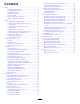
Contents Checking the Fuel Lines and Connections ..................45 Servicing the Water Separator ..................................45 Cleaning the Fuel-Intake Screen ...............................45 Electrical System Maintenance ....................................46 Charging and Connecting the Battery ........................46 Servicing the Battery...............................................47 Locating the Fuses..................................................47 Drive System Maintenance .........
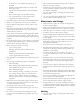
Safety • Tie back long hair. Do not wear jewelry. • Thoroughly inspect the area where the equipment is to This machine meets or exceeds EN ISO 5395:2013 (when appropriate decals applied), and ANSI B71.4-2012. • • Improperly using or maintaining the machine can result in injury. To reduce the potential for injury, comply with these safety instructions and always pay attention to the safety-alert symbol, which means Caution, Warning, or Danger—personal safety instruction.
• • • • • • • • • • • • • • Do not operate the machine when ill, tired, or under the – do not stop or start suddenly when going up or downhill; – machine speeds should be kept low on slopes and during tight turns; – stay alert for humps and hollows and other hidden hazards; – Do not turn sharply. Use care when reversing. – Use counterweight(s) or wheel weights when suggested in the operator's manual. Stay alert for holes in the terrain and other hidden hazards.
• Use full width ramps for loading machine into trailer or • On any hill, there is the possibility of tipping or rolling truck. • Tie the machine down securely using straps, chains, cable, over, but the risk increases as the slope angle increases. Steep hills should be avoided. or ropes.
Sound Pressure Level Vibration Level This unit has a sound pressure level at the operator’s ear of 83 dBA, which includes an Uncertainty Value (K) of 1 dBA. Hand-Arm Sound pressure level was determined according to the procedures outlined in EN ISO 5395:2013. Measured vibration level for left hand =0.3 m/s2 Measured vibration level for right hand =0.3 m/s2 Uncertainty Value (K) = 0.16 m/s2 Measured values were determined according to the procedures outlined in EN ISO 5395:2013.
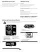
117-4766 110-9642 1. Cutting/dismemberment hazard; fan—stay away from moving parts. 1. Stored energy hazard—read the Operator's Manual. 2. Move the cotter pin to the hole closest to the rod bracket and then remove the lift arm and pivot yoke. 117–2718 106-6755 1. Engine coolant under pressure. 3. Warning—do not touch the hot surface. 2. Explosion hazard—read the Operator's Manual. 4. Warning—read the Operator's Manual. 121–5644 98-4387 1. Warning—wear hearing protection. 1. Light switch 6.
106-6754 1. Warning—do not touch the hot surface. 121–3887 2. Cutting/dismemberment hazard, fan and entanglement hazard, belt—stay away from moving parts. 1. Read the Operator’s Manual. 121–3884 1. Engine—stop 3. Engine—start 2. Engine—preheat 125–4605 112-5019 1. Power seat, 10A 6. Power supplied, 10A 2. 7. Controller, 2A Work light, 10A 3. Engine, 10A 8. Power supplied, 7.5A 4. Cigarette lighter, 10A 9. Controller, 2A 5. Infocenter, 2A 93–6681 1.
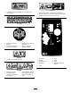
Battery Symbols Some or all of these symbols are on your battery. 120-1670 1. Traction unit speed 1. Explosion hazard 6. Keep bystanders a safe distance from the battery. 2. No fire, open flame, or smoking 7. Wear eye protection; explosive gases can cause blindness and other injuries. 3. Caustic liquid/chemical burn hazard 4. Wear eye protection. 8. Battery acid can cause blindness or severe burns. 9. Flush eyes immediately with water and get medical help fast. 3. Fast 2. Slow 5.
120-1683 1. Warning—read the Operator's Manual, do not operate this machine unless you are trained. 4. Warning—do not park the machine on slopes; engage the parking brake, lower the cutting units, stop the engine, and remove the ignition key before leaving the machine. 2. Warning—read the Operator's Manual before towing the machine. 3.
0-1686 Affix over part no. 120–1683 for CE* *This safety decal includes a slope warning required on the machine fro compliance to the European Lawn Mower Standard EN ISO 5395:2013. The conservative maximum slope angles indicated for operation of this machine are prescribed by and required by this standard. 1. Warning—read the Operator's Manual, do not operate this machine unless you are trained. 4.
Setup Loose Parts Use the chart below to verify that all parts have been shipped. Procedure Description 1 2 3 4 5 6 7 8 9 Use Qty. No parts required – Adjust the support rollers. Warning decal 1 Replace the decal for CE compliance. Hood-lock bracket Rivet Screw (1/4 x 2 inch) Flat washer (1/4 inch) Locknut (1/4 inch) Front hose guide, right Front hose guide, left 1 2 1 2 1 1 1 No parts required – Adjust the turf-compensation spring. Cutting-unit kickstand 1 Use the cutting-unit kickstand.
1 2 Adjusting the Support Rollers Replacing the Warning Decal for CE Compliance No Parts Required Parts needed for this procedure: Procedure 1 Depending on the width of the cutting units to be installed on the traction unit, adjust the support rollers as follows: Warning decal Procedure • If you are using 27-inch cutting units, install the rollers in the upper mounting holes of the support-assembly channels (Figure 3). On machines requiring CE compliance, affix the CE warning decal (Part No.
1 2 G012629 Figure 6 2. Bolt and nut assembly 1. CE lock bracket 5. Align the washers with the holes on the inside of the hood. Figure 4 1. Hood latch 6. Rivet the brackets and the washers to the hood (Figure 6). 2. Remove the 2 rivets securing the hood-latch bracket to the hood (Figure 5). 2 7. Hook the latch onto the hood-latch bracket (Figure 7). 1 1 G012630 Figure 7 G012628 1. Hood latch Figure 5 1. Hood-latch bracket 8.
4 Installing the Cutting Units Figure 10 Parts needed for this procedure: 1 1 1. Turf-compensation spring Front hose guide, right 3. Spring tube 2. Rod bracket Front hose guide, left B. Remove the flange nut securing the spring-tube bolt to the carrier-frame tab (Figure 10) 1. Remove the reel motors from the shipping brackets. C. Remove the assembly. 2. Remove the shipping brackets and discard. D. 3. Remove the cutting units from the cartons.
Figure 12 1. Cutting unit 1 5. Cutting unit 5 2. Cutting unit 2 6. Reel motor 3. Cutting unit 3 7. Weight 4. Cutting unit 4 Figure 13 1. Hose guide (left side shown) 3. Nuts 2. Rod bracket 1 1 g019602 Figure 14 1. Hose guides (each must lean toward the center cutting unit) Note: When installing or removing the cutting units, make sure that the hairpin cotter is installed in the spring-rod hole next to the rod bracket.
10. For the front cutting units, slide a cutting unit under the lift arm while inserting the shaft of the carrier frame up into the lift-arm pivot yoke (Figure 16). Make sure that the thrust washer is in position on the carrier frame shaft. 11. Secure the carrier-frame shaft to the lift-arm yoke with the lynch pin (Figure 16). 12. To lock the steering on the cutting units, secure the pivot yoke to the carrier frame with the snapper pin (Figure 17). Figure 15 1. Hex-socket screw 2. Pivot spacer 3.
5 Adjusting the Turf-Compensation Spring No Parts Required Figure 19 1. Lift-arm chain Procedure 3. Snapper pin The turf-compensation spring (Figure 21) transfers the weight from the front to the rear roller. This helps to reduce a wave pattern in the turf, also known as marcelling or bobbing. 2. Chain bracket 15. Coat the spline shaft of the reel motor with clean grease.
6 Using the Cutting-Unit Kickstand Parts needed for this procedure: 1 Cutting-unit kickstand Procedure Whenever the cutting unit has to be tipped to expose the bedknife/reel, prop up the rear of the cutting unit with the kickstand to make sure that the nuts on the back end of the bedbar adjusting screws are not resting on the work surface (Figure 22). Figure 23 1. Chain bracket 3. Cutting-unit kickstand 2.
8 Checking the Fluid Levels No Parts Required Procedure 1. Check the level of the rear axle lubricant before the engine is first started, refer to Checking the Oil Level of the Rear Axle (page 49). 2. Check the level of the hydraulic fluid before the engine is first started, refer to Checking the Level of the Hydraulic Fluid (page 32). Figure 24 3. Check the level of the engine oil before and after the engine is first started, refer to Checking the Level of the Engine Oil (page 29). 1. Gauge bar 4.
Mow-Speed Limiter Product Overview When the mow-speed limiter (Figure 26) is flipped up it will control the mow speed and allow the cutting units to be engaged. Each spacer adjusts the mowing speed by 0.8 km/h (½ mile per hour). The more spacers that there are on the top of the bolt, the slower the machine goes. For transport, flip back the mow-speed limiter and the machine will have maximum transport speed.
Bag Holder blades. Push the button back to disengage the cutting-unit blades. Use the bag holder (Figure 29) for storage. Figure 27 1. Lower mow/raise control lever 2. Key switch 4. PTO switch 5. Engine-speed switch 3. InfoCenter 6. Headlight switch Figure 29 1. Bag holder Engine-Speed Switch The engine-speed switch (Figure 27) has 2 modes to change the engine speed. By momentarily tapping the switch, the engine speed can be increased or decreased in 100 rpm increments.
Adjusting the Seat Using the InfoCenter LCD Display The InfoCenter LCD display shows information about your machine such as the operating status, various diagnostics, and other information about the machine (Figure 32) There is a splash screen and main information screen of the InfoCenter. You can switch between the splash screen and main information screen at any time by pressing any of the InfoCenter buttons and then selecting the appropriate directional arrow. 1 TORO Figure 31 1. Weight gauge 4.
InfoCenter Icon Description SERVICE DUE InfoCenter Icon Description (cont'd.
Using the Menus Engine Run To access the InfoCenter menu system, press the menu access button while at the main screen. This will bring you to the main menu. Refer to the following tables for a synopsis of the options available from the menus: Indicates the inputs, qualifiers, and outputs for starting the engine. Backlap Indicates the inputs, qualifiers, and outputs for operating the backlap function.
Machine Controller Revision Lists the software revision of the master controller. InfoCenter Revision Lists the software revision of the InfoCenter. CAN Bus Lists the machine communication bus status. Setting the Blade Count 1. In the Settings Menu, scroll down to Blade Count 2. Press the right button to change the Blade Count between 5, 8, or 11 blades. Setting the Mow Speed Protected Menus 1. In the Settings Menu, scroll down to Mow Speed.
Setting the Front and Rear Reel Speeds Specifications Although the front and rear reel speeds are calculated by inputting the number of blades, mow speed and HOC into the InfoCenter, you can manually change the setting to accommodate different mowing conditions. Note: Specifications and design are subject to change without notice. Traction Unit Specifications 1. Scroll down to the F Reel RPM, R Reel RPM, or both. 2. Press the right button to change the reel speed value.
Checking the Level of the Engine Oil Operation Note: Determine the left and right sides of the machine from the normal operating position. Service Interval: Before each use or daily The engine is shipped with oil in the crankcase; however, the oil level must be checked before and after the engine is first started. CAUTION If you leave the key in the ignition switch, someone could accidently start the engine and seriously injure you or other bystanders. The crankcase capacity is approximately 9.
CAUTION If the engine has been running, the pressurized, hot coolant can escape and cause burns. • Do not open the radiator cap when the engine is running. • Use a rag when opening the radiator cap, and open the cap slowly to allow steam to escape. Figure 35 1. Dipstick 4. If the oil is below the safe range, remove the fill cap (Figure 36) and add oil until the level reaches the Full mark. Important: Do not overfill the engine. Figure 37 1. Expansion tank 2. Check the coolant level in the radiator.
Use summer-grade diesel fuel (No. 2-D) at temperatures above -7° C (20° F) and winter-grade (No. 1-D or No. 1-D/2-D blend) below that temperature. Use of winter-grade fuel at lower temperatures provides lower flash point and cold flow characteristics which will ease starting and reduce plugging of the fuel filter. DANGER In certain conditions, fuel is extremely flammable and highly explosive. A fire or explosion from fuel can burn you and others and can damage property.
Viscosity, ASTM D445 Viscosity index, ASTM D2270 Pour point, ASTM D97 cSt @ 40°C (104°F) 44 to 48 cSt @ 100°C (212°F) 7.9 to 9.
Starting and Stopping the Engine Starting the Engine Important: Bleed the fuel system if any of the following situations have occurred: • The engine has ceased running due to lack of fuel. • Maintenance has been performed upon the fuel system components. 1. Remove your foot from the traction pedal and ensure that the pedal is in the NEUTRAL position. Note: Ensure that the parking brake is set. 2. Move the engine-speed switch to the low idle position. 3. Turn the ignition key to the RUN position.
Adjusting the Lift-Arm Counterbalance 5. Remove the key from the switch to prevent accidental starting. Checking the Interlock Switches You can adjust the counterbalance on the rear cutting-unit lift arms to compensate for different turf conditions and to maintain a uniform height of cut in rough conditions or in areas of thatch buildup. Service Interval: Before each use or daily You can adjust each counterbalance spring to 1 of 4 settings.
Adjusting the Lift-Arm Turnaround Position towing, it is best to prepare the machine for both forward and reverse pushing or towing. 1. Position the machine on a level surface, lower the cutting units, stop the engine, engage the parking brakes, and remove the key from the ignition switch. Preparing the Machine for Pushing or Towing in Reverse 2. The lift-arm switch is located behind the front right lift arm (Figure 41).
Note: Do not exceed 7 to 11 N·m (5 to 8 ft-lb) torque to close the valve. Pushing or Towing the Machine Forward Only If you need to push or tow the machine forward only, you can just rotate the bypass valve. Important: If you need to push or tow the machine in reverse, refer to Preparing the Machine for Pushing or Towing in Reverse (page 35). 1. Open the hood and remove the center shroud. 2.
Hauling the Machine Use extra care when operating the machine on slopes. Make sure that the seat latch is properly secured and the seat belt is buckled. Drive slowly and avoid sharp turns on slopes to prevent rollovers. For steering control, the cutting unit must be lowered when going downhill. • Use care when loading or unloading the machine into or out of a trailer or a truck. • Use a full-width ramp for loading or unloading the machine into or out of a trailer or a truck.
Maintenance Note: Determine the left and right sides of the machine from the normal operating position. Recommended Maintenance Schedule(s) Maintenance Service Interval Maintenance Procedure After the first 8 hours • Torque the wheel nuts. After the first 50 hours • Change the engine oil and filter. After the first 200 hours • Change the planetary gear drive oil. • Change the oil in the rear axle. • Change the hydraulic filters.
Daily Maintenance Checklist Duplicate this page for routine use. Maintenance Check Item For the week of: Mon. Tues. Wed. Thurs. Fri. Check the safety interlock operation. Check the brake operation. Check the levels of the engine oil and fuel. Check the cooling-system fluid level. Drain the water/fuel separator. Check the air-filter service indicator. Check the radiator, oil cooler, and screen for debris. Check unusual engine noises.1 Check unusual operating noises.
Notation for Areas of Concern Inspection performed by: Item Date Information 1 2 3 4 5 6 7 8 Important: Refer to your engine operator's manual and cutting unit Operator's Manual for additional maintenance procedures. Note: To obtain an electrical schematic or a hydraulic schematic for your machine, visit www.Toro.com.
CAUTION If you leave the key in the ignition switch, someone could accidently start the engine and seriously injure you or other bystanders. Remove the key from the ignition before you do any maintenance. Lubrication Premaintenance Procedures Greasing the Bearings and Bushings Removing the Hood Service Interval: Every 50 hours 1. Release the hood latches (Figure 46) and pivot open the hood. The machine has grease fittings that must be lubricated regularly with No. 2 lithium grease.
• Steering cylinder ball joints (2) (Figure 49) Figure 51 Figure 49 1. Top fitting on king pin • Tie rod ball joints (2) (Figure 49) • King pin bushings (2) (Figure 49). The top fitting on • the king pin should only be lubricated annually (2 pumps).
Engine Maintenance high-pressure air, which could force dirt through the filter into the intake tract. Servicing the Air Cleaner This cleaning process prevents debris from migrating into the intake when the primary filter is removed. 4. Remove and replace the primary filter (Figure 54). Service Interval: Every 400 hours Cleaning of the used element is not recommended due to the possibility of damage to the filter media.
Adjusting the Throttle Servicing the Engine Oil and Filter Adjust the throttle cable (Figure 58) so that the governor lever on the engine contacts the high speed set bolt at the same point that the throttle cable contacts the end of the slot in the control arm. Service Interval: After the first 50 hours Every 250 hours 1. Remove the drain plug (Figure 56) and let the oil flow into a drain pan. When the oil stops, install the drain plug. g026803 Figure 58 Figure 56 1. Throttle cable 1.
Servicing the Water Separator Fuel System Maintenance Service Interval: Before each use or daily—Drain water or other contaminants from the water separator. DANGER Every 400 hours—Replace the fuel filter canister. Under certain conditions, diesel fuel and fuel vapors are highly flammable and explosive. A fire or explosion from fuel can burn you and others and can cause property damage. 1. Place a clean container under the fuel filter. 2. Loosen the drain plug on the bottom of the filter canister.
Electrical System Maintenance DANGER Battery electrolyte contains sulfuric acid which is a deadly poison and causes severe burns. Charging and Connecting the Battery • Do not drink electrolyte and avoid contact with skin, eyes or clothing. Wear safety glasses to shield your eyes and rubber gloves to protect your hands. WARNING • Fill the battery where clean water is always available for flushing the skin.
2. Wash the entire case with a solution of baking soda and water. WARNING CALIFORNIA Proposition 65 Warning Battery posts, terminals, and related accessories contain lead and lead compounds, chemicals known to the State of California to cause cancer and reproductive harm. Wash hands after handling. 3. Rinse the case with clean water. 4. Coat the battery posts and cable connectors with Grafo 112X (skin-over) grease (Toro Part No. 505-47) or petroleum jelly to prevent corrosion.
Drive System Maintenance Checking the Torque of the Wheel Nuts Service Interval: After the first 8 hours Every 200 hours WARNING Failure to maintain proper torque of the wheel nuts could result in failure or loss of a wheel and may result in personal injury. Figure 64 Torque the front and rear wheel nuts to 115 to 136 N∙m (85 to 100 ft-lb) after 1 to 4 hours of operation and again after 8 hours of operation. Torque the wheel nuts every 200 hours thereafter. 1.
5. Repeat steps 1 through 4 on the opposite planetary gear assembly. 6. Through the open hole, slowly fill the planetary with 0.65 liters (22 ounces) of high quality SAE 85W-140 wt. gear lube. Changing the Planetary Gear Drive Oil Important: If the planetary fills before the 0.65 liters (22 ounces) of oil is added, wait one hour or install the plug and move the machine approximately ten feet to distribute the oil through the brake system. Then, remove the plug and add the remaining oil.
Changing the Oil in the Rear Axle Service Interval: After the first 200 hours Every 800 hours 1. Position the machine on a level surface. 2. Clean the area around the 3 drain plugs, 1 on each end and 1 in the center (Figure 69). Figure 70 1. Gearbox 2. Check/fill plug Adjusting the Traction Drive for Neutral Figure 69 1. Drain plugs The machine must not creep when the traction pedal is released. If it does creep, an adjustment is required. 3.
8. Remove the jack stands and lower the machine to the shop floor. 7. Rotate the entire tie-rod assembly the same direction (inward or outward) 1 complete revolution. 9. Test drive the machine to make sure that it does not creep. 8. Tighten the clamp at the connected end of the tie rod. 9. Install the ball joint in the axle case support and tighten the nut finger tight. Checking the Rear-Wheel Toe-In 10. Measure the toe-in. Service Interval: Every 800 hours/Yearly (whichever comes first) 12.
Cooling System Maintenance Servicing the Engine Cooling System Service Interval: Before each use or daily Remove debris from the engine area, oil cooler, and radiator daily. Clean them more frequently in dirty conditions. 1. Unlatch and swing open the rear screen (Figure 74). Figure 75 1. Oil cooler/radiator Important: Cleaning the oil cooler/radiator with water will promote premature corrosion damage to components and compact debris. 4. Close the rear screen and secure it with the latch. Figure 74 1.
Brake Maintenance Belt Maintenance Adjusting the Service Brakes Servicing the Alternator Belt Adjust the service brakes when there is more than 13 mm (1/2 inch) of free travel of the brake pedal, or when the brakes do not work effectively. Free travel is the distance the brake pedal moves before braking resistance is felt. Service Interval: Every 100 hours Check the condition and tension of the belts (Figure 77) after every 100 operating hours. 1.
Hydraulic System Maintenance 3. Place a drain pan under the filter and remove the filter (Figure 78 and Figure 79). 4. Lubricate the new filter gasket and fill the filter with hydraulic fluid. Changing the Hydraulic Fluid Service Interval: Every 800 hours Change the hydraulic fluid after every 800 operating hours, in normal conditions. If the fluid becomes contaminated, contact your local Toro distributor because the system must be flushed.
Checking the Hydraulic Lines and Hoses Cutting Unit Maintenance Backlapping the Cutting Units Service Interval: Before each use or daily Inspect the hydraulic lines and hoses daily for leaks, kinked lines, loose mounting supports, wear, loose fittings, weather deterioration, and chemical deterioration. Make all necessary repairs before operating. WARNING Contact with the reels or other moving parts can result in personal injury.
Storage Preparing the Engine 1. Drain the engine oil from the oil pan and install the drain plug. 2. Remove and discard the oil filter. Install a new oil filter. 3. Fill the engine with specified motor oil. 4. Start the engine and run it at idle speed for approximately 2 minutes. 5. Stop the engine. 6. Flush the fuel tank with fresh, clean fuel. 7. Secure all of the fuel-system fittings. 8. Thoroughly clean and service the air-cleaner assembly. 9.
Notes:
Notes:
International Distributor List Distributor: Agrolanc Kft Asian American Industrial (AAI) B-Ray Corporation Brisa Goods LLC Casco Sales Company Ceres S.A. CSSC Turf Equipment (pvt) Ltd. Cyril Johnston & Co. Cyril Johnston & Co. Fat Dragon Femco S.A. FIVEMANS New-Tech Co., Ltd ForGarder OU G.Y.K. Company Ltd. Geomechaniki of Athens Golf international Turizm Hako Ground and Garden Hako Ground and Garden Hayter Limited (U.K.) Hydroturf Int. Co Dubai Hydroturf Egypt LLC Irrimac Irrigation Products Int'l Pvt Ltd.
The Toro Warranty A Two-Year Limited Warranty Conditions and Products Covered The Toro Company and its affiliate, Toro Warranty Company, pursuant to an agreement between them, jointly warrant your Toro Commercial product (“Product”) to be free from defects in materials or workmanship for two years or 1500 operational hours*, whichever occurs first. This warranty is applicable to all products with the exception of Aerators (refer to separate warranty statements for these products).