
Operator's Manual


14
Alternate Adjustments
Tractors are setup at the factory appropriately for most
fairway mowing applications.
The following adjustments are available for fine-tuning of
the machine to the application:
Adjust Turf Compensation Spring
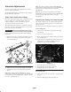
The Turf Compensation Spring (Fig. 7), connecting carrier
frame to cutting unit, controls the amount of fore-aft
rotation available, as well as the amount of ground
clearance in transport and turn around.
The Turf Compensation Spring also transfers weight from
the front to rear roller. This helps to reduce a wave pattern
in the turf, also known as bobbing.
Important Make spring adjustments with cutting
unit mounted to traction unit and lowered to shop floor.
Refer to Traction Unit Operator’s Manual for mounting
instructions.
1. Tighten lock nut on rear of spring rod until the gap (C)
between rear of spring bracket and front of washer is
1 in. (25 mm) (Fig. 7).
“C”
“A”
“B”
Figure 7
2. Tighten hex nuts on front end of spring rod until the
compressed length (A) of spring is 8 in. (203 mm)
(Fig. 7).
Note: When cutting rough or undulating turf, increase
compressed length (A) of spring to 8-1/2 in. (216 mm) and
gap (C) between rear of spring bracket and front of washer
to 1-1/2 in. (38 mm) (Fig. 7).
Note: As compressed spring length (A) DECREASES,
weight transfer from front roller to rear roller INCREASES
and carrier frame/cutting unit rotation angle (B)
DECREASES.
Note: As gap (C) between spring bracket and washer
INCREASES, cutting unit ground clearance DECREASES
and carrier frame/cutting unit rotation angle (B)
INCREASES.
Adjusting the Cutting Unit Lowering Rate
The cutting unit lift circuits are equipped with adjustable
valves to ensure the cutting units lower at the desired rate.
Adjust as follows:
Run traction unit until operating temperature is reached.
Front Cutting Units
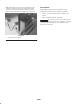
1. Locate valves under seat for adjusting front cutting
units (Fig. 8).
2. Loosen set screws securing knob.
3. Rotate appropriate valve clockwise to slow down drop
rate of cutting units.
4. Verify the lift rate adjustment by raising and lowering
cutting units several times. Readjust as required.
Tighten set screw securing adjustment.
3
1
2
3
Figure 8
1. Adjustment valve for front center cutting unit
2. Adjustment valve for front outside cutting units
3. Adjustment valves for wing cutting units
Rear Cutting Unit
1. Locate valve in front of rear axle for rear cutting units
(Fig. 9).
2. Loosen locking ring securing knob (Fig. 9).