
Operator's Manual


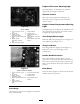


Figure 10
Model 03808
1. Lower mow/raise control
lever
7. Charge indicator
2. Fuel gauge 8. Throttle control
3. Engine coolant
temperature gauge
9. Enable/disable switch
(Master)
4. Engine oil pressure warning
light
10. Enable/disable switch (#7)
right rear
5. Engine coolant
temperature warning
light
11. Enable/disable switch (#6)
left rear
6. Glow plug indicator light
Figure 11
Models 03806 and 03807
1. Lower mow/raise control
lever
6. Glow plug indicator light
2. Fuel gauge 7. Charge indicator
3. Engine coolant
temperature gauge
8. Throttle control
4. Engine oil pressure warning
light
9. Enable/disable switch
(Master)
5. Engine coolant
temperature warning
light
Fuel Gauge
T he fuel g aug e ( Figure 10 and Figure 11 ) indicates
lev el of fuel in tank.
Engine Oil Pressure Warning Light
T his light ( Figure 10 and Figure 11 ) indicates
dang erously lo w engine oil pressure .
Throttle Control
Mo v e the control ( Figure 10 and Figure 11 )
forw ard to increase engine speed, rearw ard to
decrease speed.
Engine Coolant Temperature Warning
Light
T he light ( Figure 10 and Figure 11 ) illuminates and
the engine shuts do wn when the coolant reac hes
a dang erously high temperature .
Glow Plug Indicator Light
W hen the indicator light ( Figure 10 and Figure 11 )
is lit, indicates glo w plugs are on.
Charge Indicator
T he c harg e indicator ( Figure 10 and Figure 11 )
illuminates when system c harging circuit
malfunctions .
Enable/Disable Switches
T he enable/disable switc hes ( Figure 10 and
Figure 11 ) are used in conjunction with the lo w er
mo w/raise control lev er (J o ystic k) to operate reels .
R eels can be raised but not lo w ered when in mid
position.
Hour Meter
T he hour meter ( Figure 12 ) sho ws total hours that
mac hine has been operated.
19