
Operator's Manual


37
Adjusting Throttle
1. Position throttle lever forward so it stops against seat
base slot.
2. Loosen the throttle cable connector on the lever arm at
the injection pump.
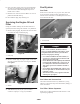
1
2
Figure 55
1. Injection pump lever arm 2. Connector
3. Hold the injection pump lever arm against the high idle
stop and tighten the cable connector.
Note: When tightened, the cable connector must be free to
swivel.
4. Torque the lock nut, used to set the friction device on
the throttle lever, to 40–55 in-lb. The maximum force
required to operate the throttle lever should be 20 lb.
Changing the Hydraulic Fluid
Change hydraulic fluid after every 800 operating hours, in
normal conditions. If fluid becomes contaminated, contact
your local Toro distributor because the system must be
flushed. Contaminated fluid looks milky or black when
compared to clean oil.
1. Turn engine off and raise hood.
2. Remove drain plug from bottom of reservoir (Fig. 56)
and let hydraulic fluid flow into drain pan. Install and
tighten plug when hydraulic fluid stops draining.
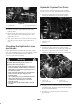
1
Figure 56
1. Hydraulic reservoir
3. Fill reservoir with approximately 8.5 gallons of
hydraulic fluid; refer to Checking the Hydraulic Fluid.
Important Use only hydraulic fluids specified. Other
fluids could cause system damage.
4. Install reservoir cap. Start engine and use all hydraulic
controls to distribute hydraulic fluid throughout the
system. Also check for leaks. Then stop the engine.
5. Check level of fluid and add enough to raise level to
FULL mark on dipstick. Do not overfill.
Replacing the Hydraulic Filter
The hydraulic system filter head is equipped with a service
interval indicator. With the engine running, view the
indicator, it should be in the GREEN zone. When the
indicator is in the RED zone, the filter element should be
changed.
Use the Toro replacement filter (Part No. 94-2621).
Important Use of any other filter may void the
warranty on some components.
1. Position machine on a level surface, lower the cutting
units, stop the engine, engage the parking brakes and
remove key from ignition switch.
2. Clean area around filter mounting area. Place drain pan
under filter and remove filter (Fig. 57).