
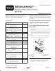
Installation Instructions

10
24. Apply a film of grease to each end of the groomer
shaft and onto the seals in the L.H. height of cut
assembly
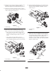
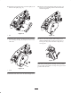
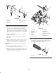
25. Carefully insert the key way end of the groomer shaft
into the LH height of cut assembly until the shaft
clicks into position (Fig. 32).Take care not to damage
the seals in the height of cut assembly.
2
1
Figure 32
1. L.H. height of cut
assembly
2. Groomer shaft
26. Apply a film of grease onto the seals in the R.H.
height of cut assembly. Insure that the O–ring is in
position on the RH end of the groomer shaft.
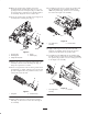
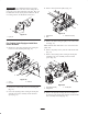
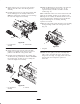
27. Carefully insert the RH height of cut assembly onto
the RH end of the groomer shaft until the shaft clicks
into position (Fig. 33).Take care not to damage the
seals in the height of cut assembly.
1
2
Figure 33
1. R.H. height of cut
assembly
2. Groomer
28. Mount the RH height of cut assembly to the right end
of the cutting unit with the (2) 3/8–16 x .75” lg
capscrews and (2) .406 ID x .812 OD x .065 thk.
washers (Fig. 33).
Note: If additional washers were used to shim out the LH
height of cut assembly, washers are not required on the
RH height of cut assembly. If additional washers were not
used on the LH side they should be used on the RH side.
Torque the RH height of cut assembly mounting
capscrews to 35 ft–lbs.
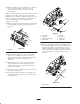
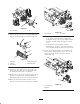
29. Slide the seal guards against the height of cut assembly
bearing housings on both ends of the groomer shaft
(Fig. 34).
1
Figure 34
1. Seal guard
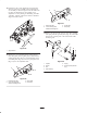
30. Mount the drive pulley to the drive assembly shaft
with a .125 x .312 square key and a .312 x .62” lg.
flange head screw (Fig. 35). Apply Loctite 242 to the
threads of the screw. Torque the capscrew to
200 in–lbs.