
Installation Instructions

1
All Rights Reserved
Printed in the USA
W 2005 by The Toro Company
8111 Lyndale Avenue South
Bloomington, MN 55420-1196
Right Hand Groomer Kit
Left Hand Groomer Kit
Reelmaster 5500–D, 6500–D & 6700–D
Model No. 03811
Model No. 03810
Form No. 3351–743 Rev B
Installation Instructions
Note: The Right and Left Groomer Kits can be used on
Reelmaster 55/6000 Cutting Unit Models 03860, 03861 &
03862 with or without a Rear Roller Brush Kit.
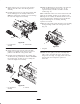
Loose Parts
Description Quantity
Drive assembly w/O–ring
Bolt M10 x 1.5
Bolt 3/8–16 x 1.25
1
2
2
Height of cut assembly–RH
Capscrew 3/8–16 x .75” lg.
Washer–.406 I.D. x .812 O.D. x .065 Thk.
Washer–.406 I.D. x .812 O.D. x .030 Thk.
1
2
8
4
Alignment tool 1
Height of cut assembly–LH
Capscrew 3/8–16 x .75” lg.
Washer–.406 I.D. x .812 O.D. x .065 Thk.
Washer–.406 I.D. x .812 O.D. x .030 Thk.
1
8
4
Groomer assembly
Seal guard
1
2
Groomer plate assembly–LH 1
Groomer plate
Brush plate–LH
1
1
Retaining plate
Flange head screw–.312 x .62” lg.
Spacer
Retaining ring
1
2
2
1
Drive pulley
Square key
Flange head screw–.312 x .62” lg.
1
1
1
Pulley spacer
Washer–.474 I.D. x .938 O.D. x .030 Thk.
Washer–.474 I.D. x .938 O.D. x .030 Thk.
Drive pulley
Square key
Flange nut–3/8–16
1
2
2
1
1
1
Belt 1
Cover (Groomer)
Cover (Brush & groomer)
Flange nut–5/16–18
1
2
2
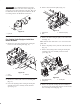
Note: These instructions and illustrations show the
installation of the Left Hand Groomer Kit onto the cutting
units with the counter weights mounted on the left end of
the cutting unit.
Use the following installation instructions if the cutting
units are not equipped with rear roller brushes. If the
cutting units are equipped with rear roller brushes,
proceed to page 6 for the installation instructions.
For Cutting Units Not Equipped with a
Roller Brush
1. Park the traction unit on a level surface and engage the
parking brake.
2. Ensure that the cutting units are disengaged. Lower the
cutting units to the ground. Turn the engine off and
remove the key. Remove all cutting units from traction
unit.
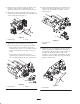
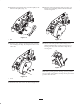
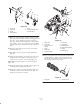
3. Remove the top cone nuts securing both front roller
support rods to the height of cut brackets (Fig. 1).
2
3
5
4
1
Figure 1
1. Front roller
2. Cone nut
3. Rod support
4. Height of cut bracket
5. Roller shaft screw
4. Loosen the roller shaft screw on one height of cut
bracket (Fig. 1). Slide the rod supports and roller
assembly out of the height of cut brackets.