
Installation Instructions

13
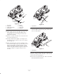
Note: After greasing groomer bearings, operate groomer
for 30 seconds, stop machine and wipe excess grease from
groomer shaft and seals.
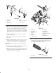
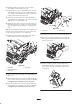
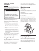
Important It is recommended that the Lynch pin
(Fig. 42) be installed on the front center cutting unit to
prevent the covers from contacting each other. Also, it is
recommended that the Lynch pin be installed on all the
rear cutting units on the Reelmaster 5500 series.
1
Figure 42
1. Lynch pin 2.
Important When a brush kits is installed, make sure
the recommended spacers and chains are properly
installed per the installation instructions included with the
Roller Brush Kit.
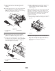
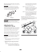
Adjusting the Turf
Compensation Spring
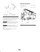
The Turf Compensation Spring (Fig. 43), connecting
carrier frame to cutting unit, controls the amount of
fore-aft rotation available, as well as the amount of
ground clearance in transport and turn around.
The Turf Compensation Spring also transfers weight
from the front to rear roller. This helps to reduce a
wave pattern in the turf, also known as bobbing.
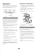
Important Make spring adjustments with cutting unit
mounted to traction unit and lowered to shop floor. Refer
to Traction Unit Operator’s Manual for mounting
instructions.
1. Tighten lock nut on rear of spring rod until the gap (C)
between rear of spring bracket and front of washer is
1” (26 mm) (Fig. 43).
2. Tighten hex nuts on front end of spring rod until the
compressed length (A) of spring is 8” (203 mm)
(Fig. 43).
Note: When cutting rough or undulating turf,
increase the compressed length (A) of
the spring to 8-1/2” (216 mm) and the
gap (C) between the rear of the spring
bracket and the front of the washer to
1-1/2” (39 mm) (Fig. 43).
Note: As the compressed spring length (A)
decreases, the weight transfer from the
front roller to the rear roller increases
and the carrier frame/cutting unit
rotation angle (B) decreases.
Note: As the gap (C) between the spring bracket
and the washer increases, the cutting
unit ground clearance decreases and
the carrier frame/cutting unit rotation
angle (B) increases.
Note: When cutting under normal conditions, the
compressed spring length (A) can be set as short as 7–1/8”
(181 mm) and the gap (C) can be set to 1-1/2” (39 mm)
to compensate for the additional weight of the
groomer attachment.
“C”
“A”
“B”
Figure 43