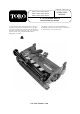
FORM NO. 3322-218 Rev A MODEL 03857—90001 AND UP MODEL 03858—90001 AND UP MODEL 03859—90001 AND UP ® OPERATOR'S MANUAL 5, 7 & 11 BLADE REELS REELMASTER 6000 SERIES To assure maximum safety, optimum performance, and to gain knowledge of the product, it is essential that you or any other operator of the machine and cutting units read and understand the contents of this manual before the engine is ever started.
This operator's manual has instructions on safety, operation, and maintenance. This manual emphasizes safety, mechanical and general product information. DANGER, WARNING and CAUTION identify safety messages. Whenever the triangular safety alert symbol appears, understand the safety message that follows. “IMPORTANT” highlights special mechanical information and “NOTE” emphasizes general product information worthy of special attention.
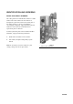
IDENTIFICATION AND ORDERING MODEL AND SERIAL NUMBERS The cutting unit has two identification numbers: a model number and a serial number. The two numbers are stamped into a plate that is located on left side plate of the cutting unit (Fig. 1). In any correspondence concerning the cutting unit, supply the model and serial numbers to assure that correct information and replacement parts are obtained. To order replacement parts from an authorized TORO Distributor, supply the following information: 1.
Safety Instructions The safety alert symbol means CAUTION, WARNING or DANGER - “personal safety instruction”. Read and under stand the instruction because it has to do with safety. Failure to comply with the instruction may result in personal injury. 1. Read and understand the contents of this Operator’s Manual before operating the cutting unit.
Safety SAFETY AND INSTRUCTION DECALS The following decal is installed on the cutting uit. If it becomes damaged or illegible, replace it. The decal part number is listed below and in your parts catalog. Replacement can be ordered from your Authorized Toro Distributor. ON FRONT SHIELD OF THE CUTTING UNIT (Part No. 93-6688) Danger! The rotating reel will cut hands and feet. Never place your hands or feet in reel area while the engine is running. Read the operator manual for maintenance procedures.
Specifications Reel Construction: Fairway reels. All welded. 5, 7 or 11 blades. Height-Of-Cut Range: 5 Blade - 3/4” to 1-1/2” (19ñ38 mm) 7 Bladeñ1/2” to 1ñ1/8” (13ñ29 mm) 11 Bladeó3/8” to 3/4” (10ñ19 mm) NOTE: Use bedknife Part No. 93-9774 for height of cuts below 1/2” (13 mm). Reel Diameter: 7 in. (178 mm) Power Attachment: Reel motors feature quick disconnect for removal or installation onto the cutting unit. Cutting units can be driven from either end.
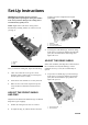
Set-Up Instructions mounting tab to the straight-ahead or angled position slot IMPORTANT: Read this operator’s manual thoroughly before operating the cutting unit. Failure to do so may result in damage to the cutting unit or an unsatisfactory quality of cut. 1 NOTE: Right and left ends of the cutting unit are determined by standing with the rear roller in front of you (Fig. 2). 2 3 2 1 Figure 3 1. Shield fin 2. Front grass shield 3. Front capscrew location 3. 3 Figure 2 1. Operator 2. Right 3.
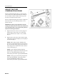
Set-up Instructions ADJUST THE TURF COMPENSATION SPRING The turf compensation spring (Fig. 5), connecting the carrier frame to the cutting unit controls the amount of fore-aft rotation available, and the amount of ground clearance in transport and turn around. The turf compensation spring also transfers weight from the front to the rear roller. This helps reduce a wave pattern in the turf. IMPORTANT: Make spring adjustments with the cutting unit mounted to the traction unit and lowered to the shop floor.
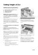
Setting Height of Cut IMPORTANT. To insure proper setting of height of cut, these procedures must be followed in this order: A. B. C. D. 1 Adjusting (Parallel) the bedknife to the reel Setting cutting unit attitude Leveling the front roller Finalizing height of cut IMPORTANT: Each cutting unit must be set consistently. Minor differences in either 1) height of cut, 2) attitude, 3) bedknife wear or 4) Reel blade wear, between cutting units, may result in negative after-cut appearance.
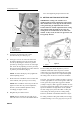
Setting Height of Cut move when tightening the pivot hub lock nuts. B. SETTING CUTTING UNIT ATTITUDE 2 3 1 IMPORTANT: Cutting unit “attitude” has a significant impact on the performance of the cutting unit. Attitude refers to the angle of the knife relative to the ground (Fig. 8). Adjustable front and rear brackets allow for variable adjustment of the cutting unit attitude within the height-of-cut range. All cutting units on a machine must be set to the same attitude.
Setting Height of Cut 98-1852 (Fig. 10). The first screw is set for height of cut, and the second screw is set for cutting unit attitude. The second screw setting is an easy method of transferring cutting unit attitude to all cutting units on a machine. “B” Figure 11 3. Figure 10 1. 2. 3. 4. 1st screw 2nd screw Height-of-cut setting Attitude Set the rear support bracket and side plate using the approximate dimensions given by Table 1.
Setting Height of Cut TABLE 1—NEW CUTTING UNIT SET-UP GUIDE Desired Height of Cut Desired Attitude 2nd Screw “A” (Fig. 14) Front Roller “B” (Fig. 11) Rear Support Bracket Hole (Fig. 12) Side Plate Hole (fig. 11) •Optional Low-Cut Bedknife, Toro part no. 93-9774, is required for a height of cut below 13mm NOTE: For front roller distances (“B”) greater than 38 mm, switch the long and short adjusting nut locations for better support (fig.
Setting Height of Cut FIRST METHOD (Angle Indicator): 1. Rotate the cutting unit backward to gain access to the reel and bedknife. 2. Place an angle indicator, Toro part no. 99-3503, on the bedknife and record the bedknife angle (Fig. 15). 1 1 2 Figure 13 1. 1st screw 2. 2nd screw Figure 15 1. Bedknife angle 3. Using a two-screw gauge bar, Toro part no. 981852, set the first screw to desired height of cut. 4. Place the gauge bar across the front and rear rollers.
Setting Height of Cut 3. 3 Place the gauge bar across the front and rear rollers. The first screw head needs to fit snugly over the edge of the bedknife, while the gauge bar contacts the front roller (Fig. 17). NOTE: The rear roller does not have to contact the gauge bar. 1 1 2 Figure 16 1. 1st screw 2. 2nd screw 3. Gauge bar angle 6. Bedknife Angle (step 2) – Gauge Bar Angle (step 5) = Cutting Unit Attitude (degrees) 7. Adjust the front roller to your desired cutting unit attitude.
Setting Height of Cut TABLE 2—USED CUTTING UNIT SET UP GUIDE Attitude (degrees) 1 2 3 4 5 6 7 8 1 9. Screw Height Difference (in) 0.028 0.057 0.085 0.114 0.142 0.171 0.200 0.228 (mm) 0.72 1.44 2.16 2.89 3.61 4.34 5.07 5.80 Put the first screw back to the normal position (screw head hooks over bedknife) and set to desired height cut (Fig. 17) 10. Place the gauge bar across front and rear rollers.
Setting Height of Cut CONTACT ALONG FULL LENGTH OF FRONT ROLLER AND REEL BLADE LEVELS FRONT ROLLER TO REEL Figure 21 2 1 Figure 20 1. REF. FLAT SURFACE (1 “ X 20” X 30” FLAT STOCK SUGGESTED) 2. BAR STOCK (11 “ X 3/4” STOCK SUGGESTED) 3. Rock the cutting unit forward (on the reel blades and steel bar) until the front roller contacts the flat surface. The reel blades and bedknife must maintain contact with the bar (Fig. 20). 4.
Setting Height of Cut bedknife. NOTE: The second screw height was determined in section B: Setting Cutting Unit Attitude. 1 1 Figure 24 1. Locknut (both sides) 5. 2 Figure 23 NOTE: Make sure the gauge bar is in contact with the front roller at all times to keep correct cutting unit attitude. 1. 1stscrew 2. 2nd screw 3. 4.
Backlapping DANGER: To avoid personal injury, never your place hands or feet in the reel area while the engine is running. Changing engine speed while backlapping may cause reels to stall. Never change engine speed while backlapping. Only backlap at idle engine speed. Never attempt to turn reels by hand or foot while the engine is running. DANGER REELS MAY STALL WHILE BACKLAPPING. DO NOT ATTEMPT TO RESTART REELS BY HAND OR TOUCH REELS WHILE BACKLAPPING.
Backlapping backlapping, turn reels OFF by moving the Lower Mow/Raise lever rearward; move the Enable/Disable switch to Disable and turn the engine OFF. After adjustments have been completed, repeat steps 5–9. 11. Backlap until a small burr develops across the entire front edge of the bedknife. 12. Repeat the procedure for all cutting units to be backlapped. 13. When backlap operation has been completed, return the backlap switch to OFF, lower the seat and wash all lapping compound off the cutting units.
Maintenance LUBRICATION 1 Each cutting unit has (7) grease fittings (Fig. 26) that must be lubricated regularly with No. 2 General Purpose Lithium Base Grease. The lubrication points are front roller (2), rear roller (2), reel bearing (2) and bedknife adjuster. IMPORTANT. Lubricating cutting units immediately after washing helps purge water out of bearings and increases bearing life. Figure 28 1. Wipe each grease fitting with a clean cloth. 2. Apply grease until pressure is felt against the handle. 1.
Maintenance 1 2 Figure 30 1. Set screw 2. Bearing adjusting nut Single-Point Spring Adjustment If the single-point adjustment assembly (Fig. 31) is removed for servicing, make sure the spring is compressed to a length of 1.25” (32 mm). This adjustment is attained by tightening the nut on knob shaft. 32 mm 1 2 Figure 31 1. Single-point adjust assembly 2.