FORM NO.
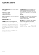
Specifications REEL CONSTRUCTION: Fairway reels. All welded. 5, CLIP FREQUENCY: .9.5 mm—31.7mm. Reel speed 7 or 11 blades automatically adjusts to maintain proper clip. Reel speed is continuously calculated based on the current forward speed, reel type (number of blades) and height of cut. HEIGHT OF CUT RANGE: 5 Blade: 19 mm to 38 mm 7 Blade: 12.7 mm to 28 mm 11 Blade:9.5 mm to 19 mm Note: Use bedknife Part No. 93-9774 for heights of cut below 12.7 mm. ROLLERS: Front rollers: 7.
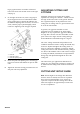
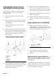
Adjusting the Cutting Unit IMPORTANT: Read this Operator’s Manual thoroughly before operating the cutting unit. Failure to do so may result in damage to the cutting unit or an unsatisfactory quality of cut. ADJUSTING THE BEDKNIFE TO THE REEL (Fig. 2–4) 1. IMPORTANT: Toro strongly recommends the use of a leveling plate when setting up or adjusting any reeltype cutting unit. The leveling plate will help to ensure accurate and consistent adjustments.
larger gap between the reel blades and the bed knife exists on the left end than exists on the right end (Fig. 4). 7. On the right end of the reel, insert a long strip of dry newspaper between reel and bedknife.
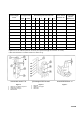
Desired Height of Cut Rear Support Hole Upper Rear Cutting Unit Side Plate Hole Lower 1 2 3 4 5 6 ••Rear Thread Distance “R” ••Front Roller Thread Distance “F” *9.5 mm X X 13.5 mm 13.9 mm *12.7 mm X X 14.2 mm 9.1 mm 15.9 mm X X 17.5 mm 6.1 mm 19.0 mm X X 13.7 mm 2.8 mm 22.2 mm X X 17.0 mm 0.0 mm 25.4 mm X X 13.2 mm –3.6 mm 28.6 mm X X 16.5 mm –6.6 mm 31.8 mm X X 12.9 mm –9.7 mm 34.9 mm X X 16.0 mm –12.9 mm 12.5 mm –16.3 mm 38.
PRELIMINARY HEIGHT-OF-CUT AND FRONT ROLLER SETTING When setting up a cutting unit, or if repositioning or installing a front or rear roller to the cutting unit, proceed as follows: 1. Verify reel-to-bedknife contact before setting height of cut. 2. Select the initial front roller bracket setting and rear roller position holes for desired height of cut (Fig. 5, 6 & CHART). 3. Position the cutting unit on a flat level surface (leveling plate). 4. Position an 11.
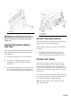
Figure 10 Figure 11 1. Gauge bar 1. Shield fin 2. Grass shield 3. Capscrew IMPORTANT: Each reel must be set consistently. Minor differences in either height of cut or attitude between cutting units may result in inconsistent quality of cut. ADJUST THE GRASS SHIELD AND FINS Adjust grass shield and/or shield fin angle for desired grass clipping dispersion. For best dispersion under most conditions: 1. Position the cutting unit on a flat level surface. 2.
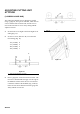
ADJUSTING CUTTING UNIT ATTITUDE 1 (2-SCREW GAUGE BAR) The cutting unit attitude may be adjusted or verified using a gauge bar, Toro part no. 98-1852, which has two screws and three hole locations. The second screw is used in the inner hole to set or verify cutting attitude. Adjust as follows: Figure 13 1. Set the front screw height to the final height-of-cut setting (Fig. 12). 2. Set the rear screw, distance “B”, lower than the front setting (Fig. 12). .20” (5.3mm) .15” (3.8mm) .09” (2.3mm) .04” (1.
Backlapping Cutting Units DANGER DANGER Reels may stall while backlapping. do not attempt to restart the reels by hand, or touch the reels while backlapping. Stop the engine and turn the height-ofcut knob one position toward “A”. To avoid personal injury, be certain that you are clear of the cutting units before proceeding. 7. Move the Enable/Disable switch to the Enable position. Move the Lower Mow/Lift control forward to start backlapping operation on designated reels. 8.
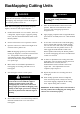
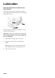
Lubrication GREASING BEARINGS, BUSHINGS AND PIVOT POINTS Each cutting unit has (6) grease fittings (Fig. 15) that must be lubricated regularly with No. 2 General Purpose Lithium Base Grease. Figure 15 The grease fitting locations shown in Figure 15 are for each side of the cutting unit. IMPORTANT: Lubricating cutting units immediately after washing helps purge water out of bearings and increases bearing life. 1. Wipe each grease fitting with a clean cloth. 2.