
Operator's Manual


PRELIMINARY HEIGHT-OF-CUT
AND FRONT ROLLER SETTING
When setting up a cutting unit, or if repositioning or
installing a front or rear roller to the cutting unit,
proceed as follows:
1. Verify reel-to-bedknife contact before setting
height of cut.
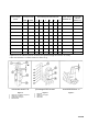
2. Select the initial front roller bracket setting and rear
roller position holes for desired height of cut (Fig.
5, 6 & CHART).
3. Position the cutting unit on a flat level surface
(leveling plate).
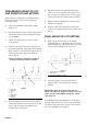
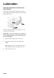
4. Position an 11.3mm or thicker bar under the reel
blades and against the cutting edge of the bedknife.
Make sure the bar covers the full length of the reel
blades. The rear roller should not contact the
surface (Fig. 8).
CONTACT ALONG FULL LENGTH AT “A’ AND “B”
LEVELS THE FRONT ROLLER TO THE REEL
Figure 8
1. Rear roller
2. Front roller
3. Reel
4. “B”
5. Flat surface
6. Bedknife
7. Bar stock
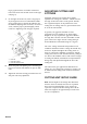
5. Rock the cutting unit forward (on the reel blades
and steel bar) until the front roller contacts the flat
surface. The reel blades and bedknife must
maintain contact with the bar.
6. Adjust the front brackets until both ends of the
roller are in contact with the level surface. Use a
piece of paper or visually check to see if any gap
exists between the roller ends and the flat surface.
7. Tighten the top and bottom nuts of the front roller
brackets to 75–88 Nm.
8. Re-check roller contact with paper to insure the
roller has not changed position and is parallel with
the reel.
FINAL HEIGHT-OF-CUT SETTING
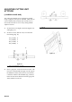
1. Using a gauge bar, Toro part no. 98-1852 or
equivalent (Fig. 9), set the head of the screw to the
desired height of cut. This measurement is from the
bar face to the underside of the screw head.
Figure 9
1. Final Height-Of-Cut Setting
2. Front Roller
3. Gauge Bar Assembly 98-1852
2. Place the gauge bar across the front and rear
rollers. Verify at each end (Fig. 10). Adjust as
required.
IMPORTANT: When set properly, front and rear
rollers will contact the gauge bar and the screw head
will be snug over the bedknife cutting edge at both
ends of the reel.
If an adjustment for desired height of cut or attitude is
required, either the front or rear roller may be adjusted.
Re-check leveling with a piece of paper and a leveling
plate after adjustments are complete.
6
1
2
3
4
5
6
7
1
2
3