Form No. 3350–284 Rev. A 5, 7 and 11 Blade Reels for Reelmasterr 5500 & 6000 Series Model No. 03860—240000001 & Up Model No. 03861—240000001 & Up Model No.
Contents 1 Page Safety . . . . . . . . . . . . . . . . . . . . . . . . . . . . . . . . . . . . . Safe Operating Practices . . . . . . . . . . . . . . . . . . . Safety and Instruction Decals . . . . . . . . . . . . . . . Specifications . . . . . . . . . . . . . . . . . . . . . . . . . . . . . . . Set–Up . . . . . . . . . . . . . . . . . . . . . . . . . . . . . . . . . . . . Loose Parts . . . . . . . . . . . . . . . . . . . . . . . . . . . . . . Inspection . . . . . . . . . . . . . . . . . . . . . . . . . .
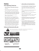
Safety • Remove all debris or other objects that might be picked up and thrown by the cutting unit reel blades. Keep all bystanders away from the mowing area. Safe Operating Practices • If the cutting blades strike a solid object or the cutting unit vibrates abnormally, stop and shut the engine off. Check cutting unit for damaged parts. Repair any damage before restarting and operating the cutting unit.
Specifications Optional Equipment Reel Construction: Fairway reels. All welded. 5, 7 or 11 blades. Dethatching Cutting Unit Model No. 03872 Grass Basket Kit Model No. 03882 Rear Roller Brush Kit Model No. 03875 High Torque Reel Motor Part No. 98-9998 Recommended Height Of Cut Range: 5 Blade – 1” to 1-3/4” (25–44 mm) 7 Blade – 1/2” to 1” (13–25 mm) 11 Blade – 3/8” to 3/4” (10–19 mm) Note: Use bedknife Part No. 93-9774 for heights-of-cut below 1/2” (13 mm).** Reel Diameter: 7 in.
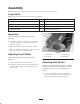
Assembly Note: Determine the left and right sides of the machine from the normal operating position. Loose Parts Note: Use the chart below to verify all parts have been shipped. DESCRIPTION QTY. USE Decal 1 Apply over existing decal for CE Operator’s Manual 1 Read before operating machine. Parts Catalog 1 Use for ordering replacement parts. Registration Card 1 Fill out and return to Toro. Inspection 3 After the cutting unit is unboxed, inspect the following: 2 1 1.
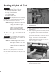
Setting Height–of–Cut Important To insure proper setting of height-of-cut, these procedures must be followed in this order: A. Adjusting (Parallel) Bedknife To Reel B. Setting Cutting Unit Attitude C. Leveling Front Roller D. Finalizing Height-of-Cut Important Each cutting unit must be set consistently. Minor differences in either height-of-cut, attitude, bedknife wear, or reel blade wear, among cutting units, may result in negative after cut appearance.
Note: If reel makes contact on both sides of bedknife but still does not cut paper, cutting unit may need to be backlapped (refer to Backlapping) and/or reel and bedknife may need to be reground (refer to Toro manual for Sharpening Reel and Rotary Mowers, Form No. 80–300PT). Note: Recheck if paper cuts on both ends, to insure the bedknife did not move when re–tightening the pivot hub lock nuts. B.
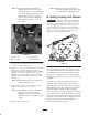
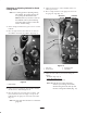
For setting consistent cutting unit attitude, Toro strongly recommends using a two-screw gauge bar, Toro part no. 98-1852 (Fig. 7). The first screw is set for height-of-cut, and the second screw is set for cutting unit attitude. The second screw setting is an easy method of transferring cutting unit attitude to all cutting units on a machine. 4 3 “B” 1 HOC SETTING ATTITUDE 2.
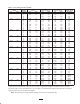
Table 1—New Cutting Unit Set Up Guide Desired Height-of-Cut (HOC) (in) (mm) 0.375 (10) 0.500 (13) 0.625 (16) 0.750 (19) 0.875 (22) 1.000 (25) 1.125 (29) 1.250 (32) 1.375 (35) 1.500 (38) 1.625 (41) 1.750 (45) Desired Attitude (degrees) 2* 4* 6* 8* 2* 4* 6* 8* 2 4 6 8 2 4 6 8 2 4 6 8 2 4 6 8 2 4 6 8 2 4 6 8 2 4 6 8 2 4 6 8 2 4 6 8 2 4 6 8 2 4 6 8 Second Screw “A” (Fig. 7) (in) (mm) 0.18 4.6 0.23 5.9 – – – – 0.29 7.6 0.35 9.0 0.41 10.5 – – 0.22 5.8 0.28 7.2 0.34 8.7 – – 0.35 9.0 0.
Checking or Adjusting Attitude for Used Cutting Units 5. Adjust second screw to contact bedknife. Move rear roller up, if needed. 6. Place an angle indicator on the gauge bar and record the gauge bar angle (Fig. 10). Note: As a starting point for adjusting cutting unit attitude, the cutting unit may be set up using the dimensions from Table 1. However, because of wear on the bedknife and reel, the following procedure must be used to ensure the correct attitude setting.
C. Leveling Front Roller Contact along full length of reel blade and front roller ends levels front roller to reel. Important Toro strongly recommends the use of a leveling plate when setting–up or adjusting any reel type cutting unit. The leveling plate will help to ensure accurate and consistent adjustments. Contact your local Toro Distributor for ordering a leveling plate. 1. Position cutting unit on a flat surface. 2.
D. Finalizing Height-of-Cut The Turf Compensation Spring also transfers weight from the front to rear roller. This helps to reduce a wave pattern in the turf, also known as bobbing. 1. Rotate the cutting unit vertical and place the gauge bar across front and rear rollers (Fig. 13). Important Make spring adjustments with cutting unit mounted to traction unit and lowered to shop floor. Refer to Traction Unit Operator’s Manual for mounting instructions. 2.
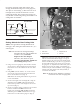
Maintenance Lubrication Each cutting unit has (7) grease fittings (Fig. 15) that must be lubricated regularly with No. 2 General Purpose Lithium Base Grease. Note: Determine the left and right sides of the machine from the normal operating position. Cutting Unit Daily Adjustments The lubrication points are front roller (2), rear roller (2), reel bearing (2) and bedknife adjuster. Prior to each day’s mowing, or as required, each cutting unit must be checked to verify proper bedknife–to–reel contact.
1 2 1 Figure 16 Figure 18 1. Bedknife adjusting knob 1. Set screw 2. Bearing adjusting nut 2. Hold on to the reel shaft and try to move the reel assembly side to side (Fig. 17). SPA (Single Point Adjustment) Spring Adjustment If single point adjustment assembly (Fig. 19) is removed for servicing, make sure spring is compressed to a length of 1.25” (32 mm). This adjustment is attained by tightening nut on SPA knob shaft. Note: SPA assembly has left-handed threads. Figure 17 1.25” (32mm) 3.
The Toro General Commercial Products Warranty A Two-Year Limited Warranty Conditions and Products Covered The Toro Company and its affiliate, Toro Warranty Company, pursuant to an agreement between them, jointly warrant your Toro Commercial Product (“Product”) to be free from defects in materials or workmanship for two years or 1500 operational hours*, whichever occurs first.