
Operator's Manual


12
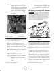
D. Finalizing Height-of-Cut
1. Rotate the cutting unit vertical and place the gauge bar
across front and rear rollers (Fig. 13).
2. Adjust rear roller until it contacts the gauge bar on
both sides (Fig. 13).
Note: Make sure gauge bar is in contact with the
front roller at all times to keep desired
height-of-cut.
3. Slide gauge bar toward the end of the cutting unit to
remove. Gauge bar can now be utilized to set
remaining cutting units on machine.
1
2
3
Figure 13
1. First screw
2. Second screw
3. Adjust rear roller
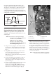
E. Adjusting Turf
Compensation Spring
The Turf Compensation Spring (Fig. 14), connecting
carrier frame to cutting unit, controls the amount of
fore-aft rotation available, as well as the amount of
ground clearance in transport and turn around.
The Turf Compensation Spring also transfers weight
from the front to rear roller. This helps to reduce a
wave pattern in the turf, also known as bobbing.
Important Make spring adjustments with cutting unit
mounted to traction unit and lowered to shop floor. Refer
to Traction Unit Operator’s Manual for mounting
instructions.
1. Tighten lock nut on rear of spring rod until the gap (C)
between rear of spring bracket and front of washer is
1” (26 mm) (Fig. 14).
2. Tighten hex nuts on front end of spring rod until the
compressed length (A) of spring is 8” (203 mm) (Fig.
14).
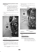
Note: When cutting rough or undulating turf,
increase compressed length (A) of
spring to 8-1/2” (216 mm) and gap (C)
between rear of spring bracket and
front of washer to 1-1/2” (39 mm)
(Fig. 14).
Note: As compressed spring length (A)
decreases, weight transfer from front
roller to rear roller increases and
carrier frame/cutting unit rotation angle
(B) decreases.
Note: As gap (C) between spring bracket and
washer increases, cutting unit ground
clearance decreases and carrier
frame/cutting unit rotation angle (B)
increases.
“C”
“A”
“B”
Figure 14