Form No.
Introduction Thank you for purchasing a Toro product. All of us at Toro want you to be completely satisfied with your new product, so feel free to contact your local Authorized Service Dealer for help with service, genuine Toro replacement parts, or other information you may require. Whenever you contact your Authorized Service Dealer or the factory, always know the model and serial numbers of your product.
Contents Safety . . . . . . . . . . . . . . . . . . . . . . . . . . . . . . . . . Safe Operating Practices . . . . . . . . . . . . . . Safety and Instruction Decals . . . . . . . . . . . Specifications . . . . . . . . . . . . . . . . . . . . . . . . . . . Set–Up . . . . . . . . . . . . . . . . . . . . . . . . . . . . . . . . Loose Parts . . . . . . . . . . . . . . . . . . . . . . . . . Inspection . . . . . . . . . . . . . . . . . . . . . . . . . . Adjusting Front Shield . . . . . . . . . . . . . . . .
Safety • Read, understand, and follow all instructions in the traction unit operator’s manual before operating the cutting unit. Lower the cutting units to the ground and remove key from ignition switch whenever machine is left unattended. • Read, understand, and follow all instructions in this operator’s manual before operating the cutting unit. Be sure cutting units are in safe operating condition by keeping nuts, bolts and screws tight.
Safety Safety and Instruction Decals Safety decals and instructions are easily visible to the operator and are located near any area of potential danger. Replace any decal that is damaged or lost. ON FRONT SHIELD OF CUTTING UNIT (Part No.
Specifications Reel Construction: Fairway reels. All welded. 5, 7 or 11 blades. Recommended Height Of Cut Range: 5 Blade – 1” to 1-3/4” (25–44 mm) 7 Blade – 1/2” to 1” (13–25 mm) 11 Blade – 3/8” to 3/4” (10–19 mm) Note: Use bedknife Part No. 93-9774 for heights-of-cut below 1/2” (13 mm). Rollers: Front roller is a 3” (76 mm) diameter cast Wiehle roller. Rear roller is a 3” (76 mm) diameter steel full roller.
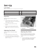
Set–Up Loose Parts Note: Use the chart below to verify all parts have been shipped. DESCRIPTION QTY. USE Operator’s Manual 1 Read before operating machine. Parts Catalog 1 Use for ordering replacement parts. Registration Card 1 Fill out and return to Toro. Inspection 3 2 1 After the cutting unit is unboxed, inspect the following: 1. Check each end of the reel for grease. Grease should be visibly evident in the reel bearings and internal splines of reel shaft. 2.
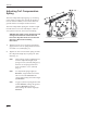
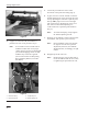
Set–Up Adjusting Turf Compensation Spring The Turf Compensation Spring (Fig. 2), connecting carrier frame to cutting unit, controls the amount of fore-aft rotation available, as well as the amount of ground clearance in transport and turn around. “B” “A” “C” The Turf Compensation Spring also transfers weight from the front to rear roller. This helps to reduce a wave pattern in the turf, also known as bobbing.
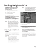
Setting Height-of-Cut IMPORTANT: To insure proper setting of height-of-cut, these procedures must be followed in this order: Note: A. Adjusting (Parallel) Bedknife To Reel B. Setting Cutting Unit Attitude C. Leveling Front Roller A 3/4 inch (19 mm) wrench is needed to rotate bedknife adjustment knob. Each notch on the knob will move the bedknife 0.0005 inches (.013 mm) closer to the reel (Fig. 3). D. Finalizing Height-of-Cut IMPORTANT: Each cutting unit must be set consistently.
Setting Height-of-Cut RIGHT 5. Loosen the pivot hub lock nuts to allow movement of the pivot hub casting (Fig. 5). 6. If paper was not cut on the left side: loosen the bottom adjusting nut on the pivot hub, then turn the top adjusting nut clockwise to pull the pivot hub up. OR If paper was not cut on the right side: loosen the top adjusting nut on the pivot hub, then turn the bottom adjusting nut counterclockwise to push the pivot hub down (Fig. 5). Note: LEFT Figure 4 4. 7.
Setting Height-of-Cut B. Setting Cutting Unit Attitude IMPORTANT: Cutting unit “attitude” has a significant impact on the performance of the cutting unit. Attitude refers to the angle of the bedknife relative to the ground (Fig. 6). Adjustable front and rear brackets allow for variable adjustment of cutting unit attitude within the height-of-cut range. All cutting units on a given machine must be set to the same attitude, otherwise after-cut appearance could be negatively affected.
Setting Height-of-Cut Table 1—New Cutting Unit Set Up Guide Desired Height-of-Cut (HOC) (in) (mm) 0.375 (10) 0.500 (13) 0.625 (16) 0.750 (19) 0.875 (22) 1.000 (25) 1.125 (29) 1.250 (32) 1.375 (35) 1.500 (38) 1.625 (41) 1.750 (45) Desired Attitude (degrees) 2* 4* 6* 8* 2* 4* 6* 8* 2 4 6 8 2 4 6 8 2 4 6 8 2 4 6 8 2 4 6 8 2 4 6 8 2 4 6 8 2 4 6 8 2 4 6 8 2 4 6 8 2 4 6 8 Second Screw “A” (Fig. 7) (in) (mm) 0.180 4.6 0.231 5.9 – – – – 0.299 7.6 0.356 9.0 0.414 10.5 – – 0.228 5.8 0.285 7.
Setting Height-of-Cut 3. Rotate the cutting unit backward to gain access to reel and bedknife. 4. Set the front height-of-cut rod height,“B,” using the dimension given in Table 1. This measurement is between the top surface of the height-of-cut rod and top cone nut (Fig. 8). 5. Set the rear support casting in either the top or bottom location as indicated in Table 1. Set the rear height-of-cut rod height .
Setting Height-of-Cut Checking or Adjusting Attitude for Used Cutting Units Note: As a starting point for adjusting cutting unit attitude, the cutting unit may be set up using the dimensions from Table 1. However, because of wear on the bedknife and reel, the following procedure must be used to ensure the correct attitude setting. 1. Rotate cutting unit backward to gain access to reel and bedknife. 2. Place an angle indicator, Toro Part No. 99–3503, on the bedknife and record the bedknife angle (Fig.
Setting Height-of-Cut 7. Adjust the front roller to your desired cutting unit attitude: Bedknife Angle (step 2) – Gauge Bar Angle (step 6) = Cutting Unit Attitude (degrees) Note: Moving the front roller down will decrease your cutting unit attitude, while moving the front roller up will increase cutting unit attitude (Fig. 10). C. Leveling Front Roller IMPORTANT: Toro strongly recommends the use of a leveling plate when setting–up or adjusting any reel type cutting unit.
Setting Height-of-Cut Note: If leveling the front roller causes the cutting unit attitude to be different from side to side by more than one degree, you may need to regrind the reel and/or bedknife to eliminate uneven wear. D. Finalizing Height-of-Cut 1. Rotate the cutting unit vertical and place the gauge bar across front and rear rollers (Fig. 13). 2. Adjust rear roller until it contacts the gauge bar on both sides (Fig. 13). 1 Figure 12 2 3 Figure 13 1. First screw 2. Second screw Note: 3.
Maintenance Backlapping Reelmaster 5500 Traction Units 2 1 1 2 POTENTIAL HAZARD • Reels may stall when backlapping. WHAT CAN HAPPEN • Reels may restart. Contact with rotating reels will cause serious injury. HOW TO AVOID THE HAZARD • Do not attempt to restart reels by hand or touch reels while backlapping. • Stop engine and turn height-of-cut knob one position toward “1.” Figure 14 1. Reel speed selector knob Note: Note: 1.
Maintenance speed selector knob(s) one position closer to “13.” Resume backlapping by moving the Lower Mow/Lift control lever forward. POTENTIAL HAZARD • Changing engine speed while backlapping may cause reels to stall. WHAT CAN HAPPEN • Reels may restart. Contact with rotating reels will cause serious injury. 10. To make an adjustment to the cutting units while backlapping, turn reels OFF by moving the Lower Mow/Raise lever rearward; move the Enable/Disable switch to Disable and turn the engine OFF.
Maintenance Backlapping Reelmaster 6000 Traction Units 1 POTENTIAL HAZARD • Reels may stall when backlapping. WHAT CAN HAPPEN • Reels may restart. Contact with rotating reels will cause serious injury. HOW TO AVOID THE HAZARD • Do not attempt to restart reels by hand or touch reels while backlapping. • Stop engine and turn height-of-cut knob one position toward “A.” Note: 1. Figure 17 1.
Maintenance 9. POTENTIAL HAZARD • Changing engine speed while backlapping may cause reels to stall. WHAT CAN HAPPEN • Reels may restart. Contact with rotating reels will cause serious injury. HOW TO AVOID THE HAZARD • Never place hands or feet in reel area while engine is running. • Never change engine speed while backlapping. • Only backlap at idle engine speed. • Never attempt to turn reels by hand or foot while engine is running. 6.
Maintenance 13. When backlap operation has been completed, return the backlap switch to OFF, lower seat and wash all lapping compound off cutting units. Adjust cutting unit reel to bedknife as needed. Reel Bearing Adjustment To insure long life of the reel bearings, periodically check if reel end play exits. The reel bearings can be checked and adjusted as follows: IMPORTANT: If the backlap switch is not returned to OFF position after backlapping, the cutting units will not raise or function properly.
Maintenance 3. If end play exists, proceeded as follows: A. Loosen set screw securing bearing adjusting nut to bearing housing located on the left side of the cutting unit (Fig. 23). B. Using a spanner wrench, slowly tighten the reel bearing adjustment nut until no end play of the reel exists. If adjusting nut does not eliminate reel end play, replace reel bearings. Note: C. SPA (Single Point Adjustment) Spring Adjustment If single point adjustment assembly (Fig.
The Toro General Commercial Products Warranty A Two-Year Limited Warranty Conditions and Products Covered The Toro Company and its affiliate, Toro Warranty Company, pursuant to an agreement between them, jointly warrant your 1996 or newer Toro Commercial Product (“Product”) purchased after January 1, 1997, to be free from defects in materials or workmanship for two years or 1500 operational hours*, whichever occurs first.